63
Ref. Component descrition Ref. Component description
AP1 Printed circuit board SA2 Cutting Emergency device switch
D1 24V DC counter ( by request ) SB1 Push--button no. 1 microswitch
FU1 Transformer primary fuse (1 A) SB2 Push--button no. 2 microswitch
M1 Pump motor SB3 Push--button no. 3 microswitch
QM1 Pump motor magnetothermic switch (by request) SB4 2--hand control push--button microswitch
QS1 Main switch SQ1 Cutting stroke--end
R1 Push--button N.1 cutting pressure potentiometer TC1 Transformer (140 VA)
R2 Push--button N.3 cutting pressure potentiometer YV1 Cutting electro valve coil
SA1 Counter exclusion switch ( by request )
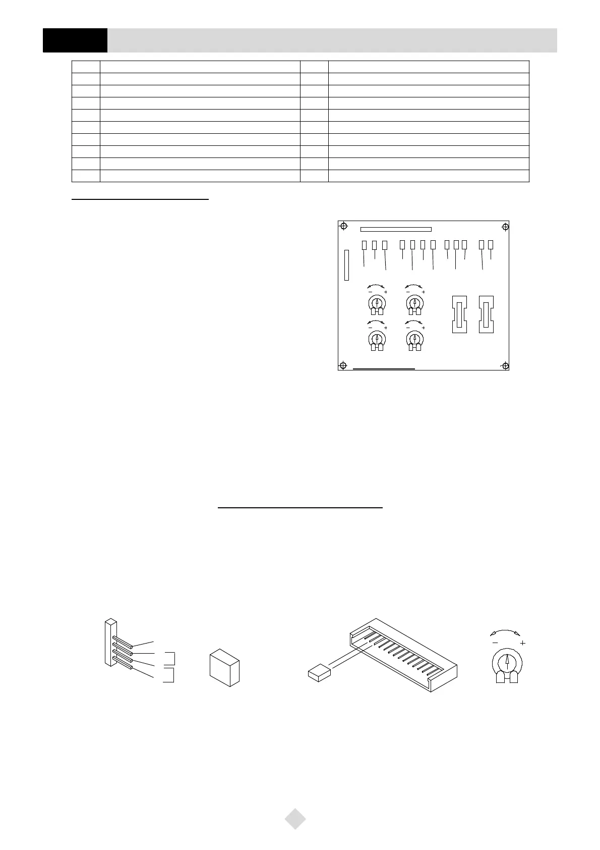
Description of led functions
D24 = +5V
cc
printed circuit board feeding signalling led
D25 = +24V
cc
printed circuit board feeding signalling led
D28 = +45V
cc
electro--valve feeding signalling led
D27 = Cutting 2 -- hand control signalling led
D29 = Pushbutton 1 signalling led (S/SE)
D30 = Pushbutton 2 signalling led (S/SE)
D31 = Pushbutton 3 signalling led (MF/S/SE)
D26 = Arm descent/ascent signalling led
(ON during: arm stand by/descent/ascent phase)
(OFF during: cutting phase)
D36 = Printed circuit card operation
D37 = Cutting electro--valve operation signalling led
D34 = MF operation signalling led
D35 = S/SE operation signalling led
F2 = 1A protection fuse
F3 = 6.3A protection fuse
T1 = Pushbutton 3 minimum pressure adjustment
T2 = Pushbutton 2 delay adjustment (applied to the printed circuit board)
T3 = Impulse suppressor adjustment (to zero)
T4 = General delay adjustment (pushbutton box)
Printed circuit board adjustments
In case of replacement of the printed circuit board it is necessary to make the following adjustments (Fig. 35):
1 -- Before to set up the new printed circuit board to connect the A jumper to the pin 14--13 of the connector J3 in case the machine DOESN’T make
use of the Identicut cutting device.
2 -- To connect the B jumper of the connector J1 to the pin 1--2 when tha machine is a MF model or to the pin 2--3 when the machine is a S/SE model.
3 -- To adjust the T3 trimmer
-- to reset (complete anticlockwise rotation) when the machine is a MF model
-- to rotate clockwise untill the swinging arm makes a correct cutting (uninterruptedly descent) when the machine is a S/SE model.
1
2
3
4
MF
S/SE
A
J1
T3
B
J3
14
13
IDENTICUT EXCLUSION
1130 S100 Wiring diagram nomenclature
GB
D25
D24
F2
F3
D27
D28
D29
D30
D31
D26
D36
D37
D34
D35
T3
LS 02E03947 -- 2
J1
J3
T4
T1T2
 Loading...