| 21
CAST IRON FLOOR STANDING GAS BOILER
/1
]å
)
/
/
1
3(
-
-
-
-
-
5±N:
KP P K P K
W
W
UU
K
P
P
K
PKK
þ
þ
P
P
K
K
P
]å
0
KP KKPK
PK
]å
K
K
P
K
K
K
þ
P
K
]å
K
P
K
K
]å
K
K
K
K
þ
þ
K
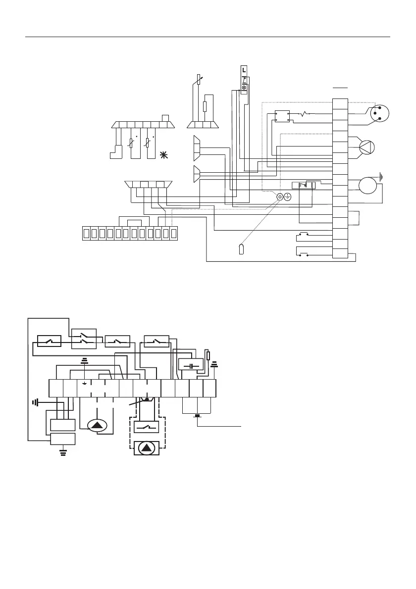
Connecting the electrical installation of the ATTACK EZ boiler
Connecting the electrical installation of the ATTACK E boiler
ATTENTION:
Connect the TP (room ther-
mostat), eventually the TV
(three-way valve) as well into
the terminals 7 and 8.
Remove the interconnection!
DESCRIPTION:
A – automatics V 4100Q
TP – room thermostat
C – capacitor
A1 – two-stage regulator of
automatics
V – main switch
TK – boiler thermostat PRODIGY
OČ – circuit pump
PR – output switch
HT – emergency thermostat
with reset
ST – flue gas thermostat with reset
TV – three-way valve Honey-
well VC4613
O – orange conductor of the
three-way valve
S – grey conductor of the
three-way valve
a9+]
3(
818
8
1
818
$
$
+7
7.
9
&
2ý
67
79
62
33
ý(53$'/2
73
73
Grounding of
the controller
* Note: if the D.H.W. tank is not connected, it is necessary to remove the sensor of the tank
and to replace it with the interconnection!
Three-way
valve
Room
thermostat
Pump Mains supply
Terminal
Boiler thermostat
Potentiometer
Mains
switch
Terminal of the gas valve’s electronics
Sensor of
heating
Connector of
modulator
Sensor of
the tank
summer / winter
Filter
Emergency thermostat
with reset
Flue gas thermostat
with reset
DESCRIPTION:
č – Black
m – Blue
h – Brown
z/ž – Yellow-green
PUMP
Interconnection