8 |
er. When mounting back, it is necessary to pay attention to seal the draught breaker with the boiler
body tightly. The function of draught breaker is described in a separate part. Under the exchanger
is the burning chamber with atmospheric burners. The bottom of the chamber is equipped by a
dish on stands to keep condensate. The burner set consists of burner tubes holder with accesso-
ries and of burning system. It is connected to the burning chamber in two points. Gas distributor
is made as a closed steel profile. On the burner board there are burner tubes. Above them there
is an ignition burner together with thermocouple (ionization electrode) and ignition electrode in
a separated holder. The ignition burner and burning level can be watched through a small hole
above the holder of burning system. This part is accessible after removing the front door. Behind
the door there is an electromagnetic combined valve positioned on the gas supply pipe, which is
one of the main functional parts of the boiler. This valve is set up by a producer to the optimal burn-
ing quality and there should be no manipulation with it. Due to this is the regulation screw painted.
Under the valve there is a holder on the gas distributor (EKO, PLQ, P) with a piezoelectric ignitor
used for starting the ignition burner. Above the valve near the upper edge of the front door there is
a covered electroinstallation board with all the electroinstallation. The boiler body is protected by
a protective coating. The external cover is treated by heat resistant dust paint.
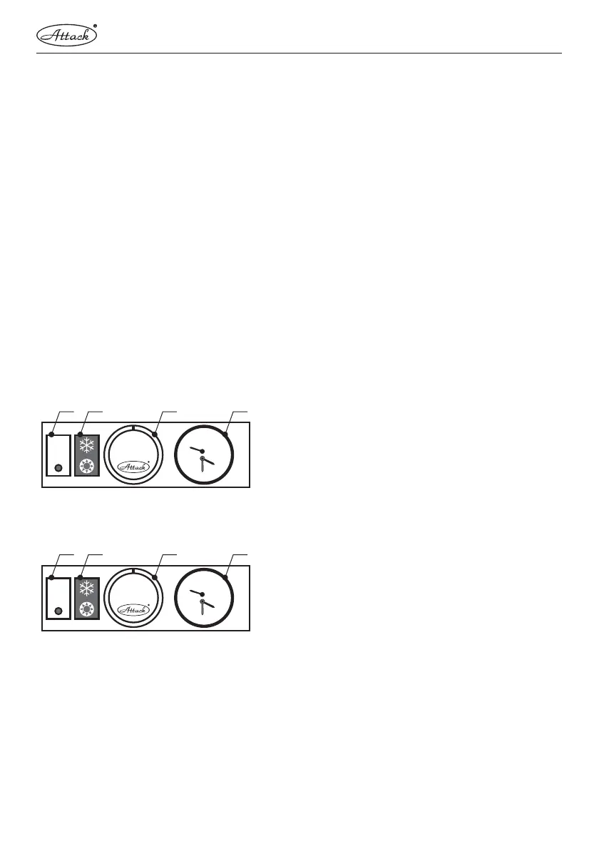
ELECTRICAL FRONT PANEL OF THE EKO, PLQ, KLV, KLQ, E BOILERS
HV – main switch
PR – operation mode switch (only PLQ, KLQ)
KT – boiler thermostat (1–5)
KT – PRODIGY "E" boiler thermostat
ZD – thermomanometer
ELECTRICAL FRONT PANEL OF THE EZ BOILERS
HV – main switch – switch of the tank (EZ)
TD – unblock button (EZ)
KP – adjustable boiler potentiometer
ZD – combined thermomanometer