Do you have a question about the AUDAC CAP412 and is the answer not in the manual?
| Channels | 4 |
|---|---|
| Output Power (RMS) per channel @ 4 Ohms | 120 W |
| Bridged Output Power (RMS) @ 8 Ohms | 240 W |
| Frequency Response | 20 Hz - 20 kHz |
| Signal-to-Noise Ratio | > 100 dB |
| THD+N | < 0.05% |
| Damping Factor | > 200 |
| Type | Power Amplifier |
| Input Impedance | 20 kΩ |
| Protection | Overload, Short Circuit, Thermal |
Unit contains no user-serviceable parts. Refer all servicing to qualified personnel.
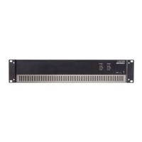
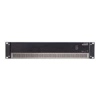
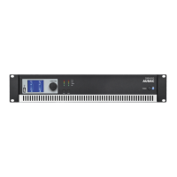
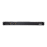
Details the power switch and indicator LEDs on the front of the amplifier.
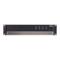
Describes AC power inlet, filter switch, gain control, speaker and input connections.
Details how to connect input signals using balanced XLR connectors for input and link.
Explains XLR wiring standards for audio equipment signal connections.
Details how to connect loudspeakers using Euro Terminal Blocks for various impedances.
Guidance on connecting loudspeakers in constant voltage systems (100V/70V).
Warning against mixing low impedance and constant voltage outputs on the same channel.
Provides detailed performance, electrical, and physical specifications for the CAP412.