Protected by copyright. Copying for private or commercial purposes, in part or in whole, is not
permitted unless authorised by AUDI AG. AUDI AG does not guarantee or accept any liability
with respect to the correctness of information in this document. Copyright by AUDI AG.
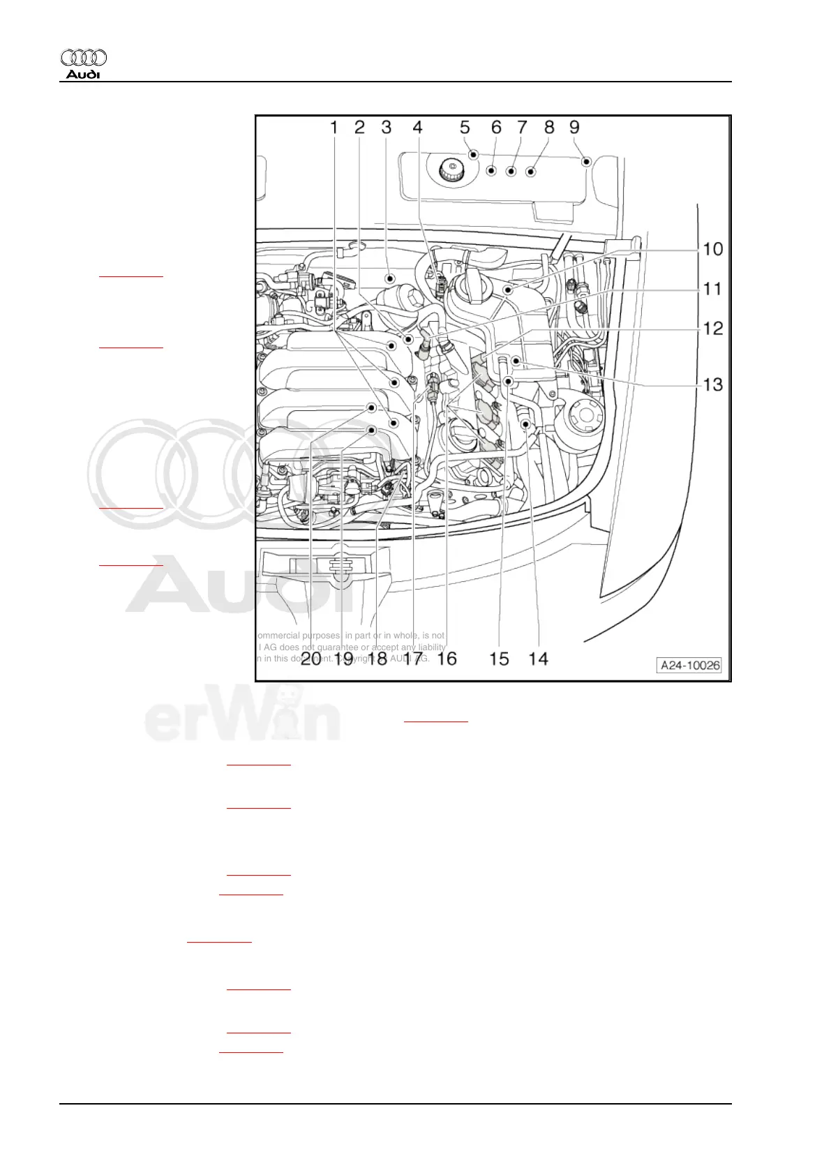
1 - Fuel injectors, cylinder bank
2
❑ Cylinder 4 fuel injector -
N33-
❑ Cylinder 5 fuel injector -
N83-
❑ Cylinder 6 fuel injector -
N84-
❑ Removing and installing
⇒ page 35 .
2 - Intake manifold runner po‐
sition sensor 2 -G512-
❑ Component location
⇒ page 14
❑ After replacing, adapt in
“Guided Fault Finding”
operating mode under
“Adapting intake mani‐
fold runner position sen‐
sor”
3 - Engine speed (RPM) sen‐
sor -G28-
❑ Component location
⇒ page 14
4 - Left holder for connectors
❑ Connector locations
⇒ page 11
5 - Instrument cluster
❑ With Malfunction Indica‐
tor Lamp (MIL) -K83-
and Electronic Power
Control (EPC) warning
lamp -K132-
6 - Throttle Position (TP) sen‐
sor -G79- / accelerator pedal position sensor 2 -G185-
❑ In accelerator pedal module, component location ⇒ page 10
7 - Brake light switch -F- / Brake pedal switch -F47-
❑ Component location ⇒ page 10
8 - Clutch pedal starter interlock switch -F194- and clutch position sensor -G476-
❑ Component location ⇒ page 10
9 - Relay box
10 - Oxygen Sensor (O2S) 2 behind Three Way Catalytic Converter (TWC) -G131-
❑ Component location ⇒ page 11
❑ Connector location ⇒ page 11
11 - Camshaft adjustment valve 2 -N208-
Component location ⇒ page 12
12 - Camshaft adjustment valve 2 (exhaust) -N319-
❑ Component location ⇒ page 12
13 - Heated Oxygen Sensor (HO2S) 2 -G108-
❑ Component location ⇒ page 11
❑ Connector location ⇒ page 11
Audi A6 2005 ➤
Fuel Injection and Ignition - Edition 03.2008
8 Rep. Gr.24 - Fuel injection system

 Loading...