38
Engine Management
Function diagram
4.2/3.7 l in A8 GP
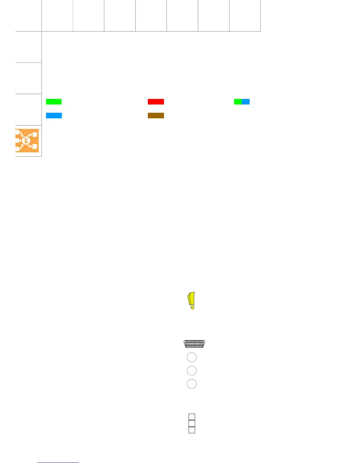
Colour coding
= Positive
= Earth
= Input signal
= Output signal
Components
A Battery
E45 Cruise control system
switch
D Ignition/starter switch
F Brake light switch
F36* Clutch pedal switch
(with manual gearbox only)
F47 Brake pedal switch for cruise control
system
G2 Coolant temperature sender
G3 Coolant temperature gauge
G6 Fuel pump
G28 Engine speed sender
G39 Lambda probe
G40 Hall sender
G61 Knock sensor 1
G62 Coolant temperature sender
G66 Knock sensor 2
G70 Air mass meter
G79 Accelerator position sender
G108 Lambda probe 2
G163 Hall sender 2
G185 Accelerator position sender 2
G186 Throttle valve drive
(electric throttle operation)
G187 Angle sender 1 for throttle valve drive
G188 Angle sender 2 for throttle valve drive
J17 Fuel pump relay
J220 Motronic control unit
J299 Secondary air pump relay
M9 Brake light bulb (left)
M10 Brake light bulb (right)
N Ignition coil (cylinder 1)
N30 Injector (cylinder 1)
N31 Injector (cylinder 2)
N32 Injector (cylinder 3)
N33 Injector (cylinder 4)
N80 Activated charcoal filter system solenoid
valve
N83 Injector (cylinder 5)
N84 Injector (cylinder 6)
N85 Injector (cylinder 7)
N86 Injector (cylinder 8)
N112 Secondary air inlet valve
N128 Ignition coil 2
= Bidirectional
Additional signals and connections
K diagnosis connection
1 Crash signal (in) from airbag control unit
2 Air conditioner requirement signal (in)
3 Air conditioner compressor signal (in-out)
CAN-BUS L } Connection to data bus
CAN-BUS H }
X}
Y } Connections in function
Z } diagram
N144 Solenoid valve (left) for electro/hydraulic
engine mounting
N145 Solenoid valve (right) for electro/hydraulic
engine mounting
N156 Intake manifold changeover valve
N158 Ignition coil 3
N163 Ignition coil 4
N164 Ignition coil 5
N189 Ignition coil 6
N190 Ignition coil 7
N191 Ignition coil 8
N205 Camshaft adjustment valve 1
N208 Camshaft adjustment valve 2
N261 Intake manifold changeover valve 2
P Spark plug connector
Q Spark plugs
S Fuse
ST Fuse holder
V101 Secondary air pump motor
Z19 Lambda probe heating
Z28 Lambda probe heating 2
S204 Fitting location in Audi A6: plenum chamber
next to battery
Fitting location in Audi A8: top right
in luggage compartment