27
Increasing torque by means of variable intake
manifolds is a tradition at Audi. A three-stage
variable intake manifold made of a die-cast
magnesium alloy, a further development of
previous concepts, is to be used for the first
time.
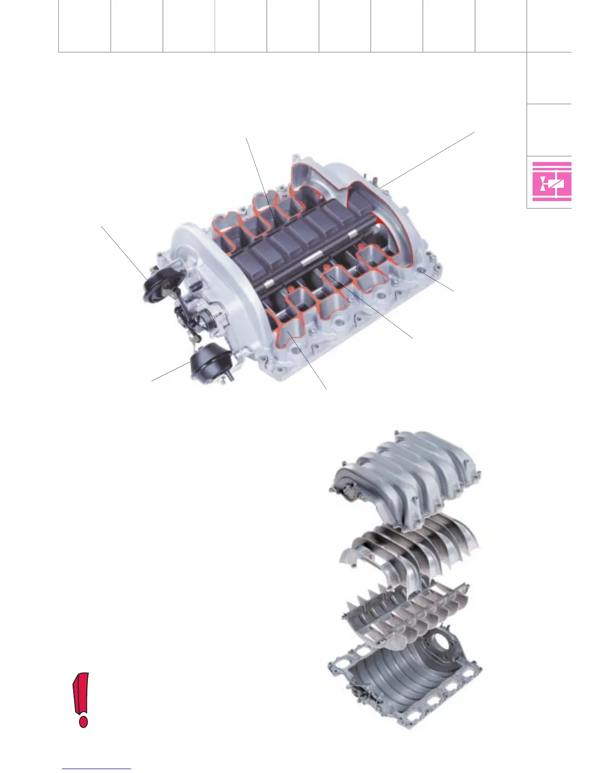
The variable intake manifold consists of four
principal housing components which are
bonded and bolted together.
The concept uses two intake manifold flaps to
produce three different intake manifold
lengths (“resonance tube lengths“). To utilise
the pulsations to optimum effect, the intake
manifold flaps close the resonance tube
openings by means of a circumferential,
moulded-on sealing lip.
SSP217_030
Holders for
injectors
The variable intake manifold must not
be dismantled. If necessary, the
entire assembly must be completely
replaced.
Variable intake manifold
Intake module
SSP217_031
Intake manifold flap, stage 3
From E-throttle
valve system
Intake air (inlet)
Intake manifold flap,
stage 2 (open)
Resonance tube, cyl. 5
(inlet side)
Vacuum unit
Intake manifold flap,
stage 2
Vacuum unit
Intake manifold flap, stage 3
Engine - Motronic Subsystems