Section 5: Digital Power Supply PCB
In this section we will be building, installing and testing the Digital Power Supply PCB that is used in the DAC2.1 and 3.1
kits.
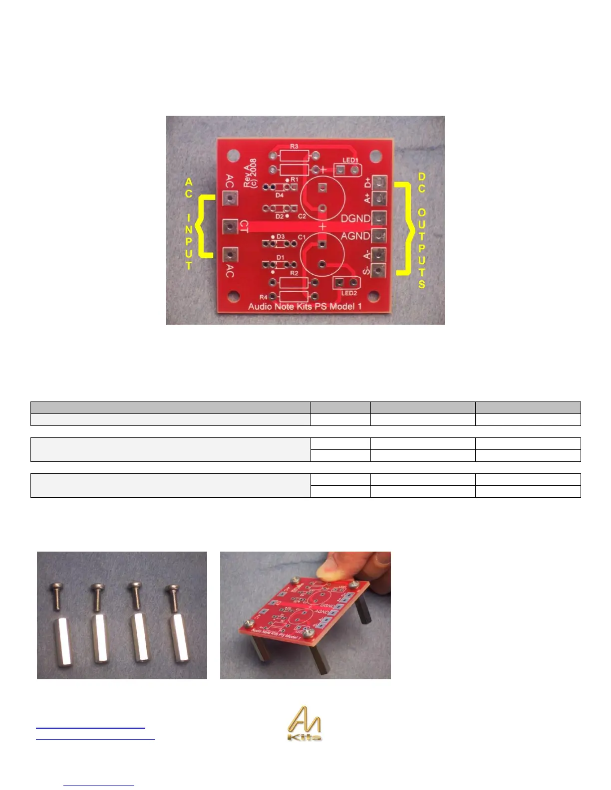
EXPLANATION: This small board receives an 18V AC signal from the 9-0-9 taps on the Mains transformers and converts
it to several DC voltages that are required by the DAC board. The outputs are A+ - AGND - A- , D+ and DGND.
Parts List
Start by installing the 4 spacers
provided. This will make it easier to
work with as we install the
components onto the board.
If you are an advanced builder we
suggest you read through this section
completely and then proceed with your
build from the parts list – otherwise we
suggest you work through each step in
the order suggested.