3
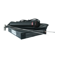
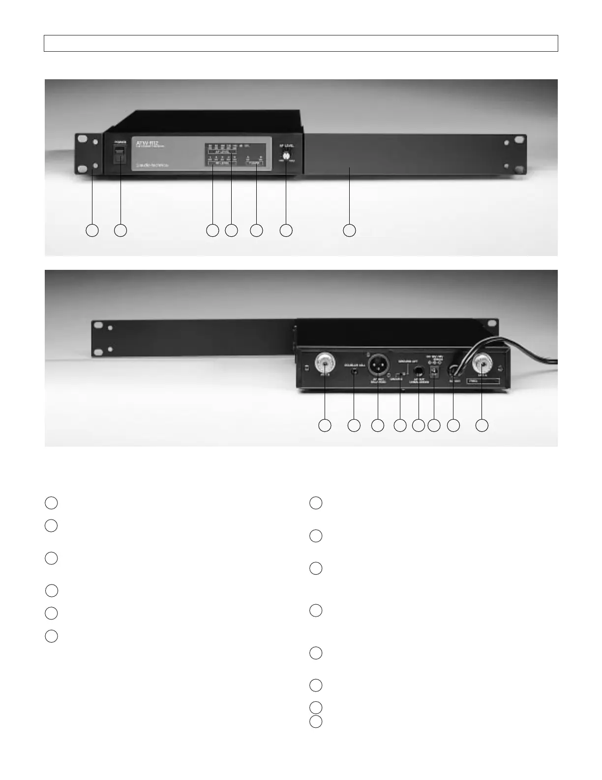
Rear Panel Controls and Functions (Fig. D)
7 TUNER “B” ANTENNA JACK: Antenna connector for
tuner “B.” Attach the antenna directly, or extend it
with an antenna cable.
8 SQUELCH CONTROL: Adjusts level of noise-muting
circuit (preset at factory but can be adjusted as
circumstances warrant).
9 BALANCED AUDIO OUTPUT JACK: XLRM-type connec-
tor. A standard 2-conductor shielded cable can be used
to connect the receiver output to a balanced microphone
level input on a mixer.
10 GROUND LIFT SWITCH: Disconnects the ground pin of
the balanced output (9) from ground. Normally, the
switch should be to the left (ground connected). If hum
caused by a ground loop occurs, slide switch to the right.
11 UNBALANCED AUDIO OUTPUT JACK:
1
⁄
4
" phone jack.
Can be connected to an unbalanced aux-level input of a
mixer or tape recorder.
12 DC POWER INPUT: For an external 12-18V DC source
(requires 350 mA).
13 AC POWER: Power cord for 120V AC power input.
14 TUNER “A” ANTENNA JACK: Antenna connector for
tuner “A.” Attach the antenna directly, or extend it
with an antenna cable.
3
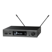
Front Panel Controls and Functions (Fig. C)
1 POWER SWITCH/INDICATOR: Press switch on, and
the “power” indicator will light.
2 RF SIGNAL LEVEL INDICATOR: Indicates the strength
of the RF signal received from the transmitter. The
LEDs will light up from left to right.
3 AF LEVEL INDICATOR: Indicates the audio modulation
level of the received signal. (Not affected by the
setting of the AF Level control.)
4 TUNER OPERATION INDICATOR: Indicates which
tuner has the better reception and is in operation.
5 AF LEVEL CONTROL: Adjusts the level at both audio
output jacks.
6 MOUNTING ADAPTERS: For mounting the receiver in
any standard 19” rack. Attach to receiver with screws
supplied. (Use optional AT8628 joining plate kit to
mount two receivers side-by-side.)
Receiver Controls And Functions
Fig. C Receiver Front Panel
Fig. D Receiver Rear Panel
5431 6
131211
97
14
6 2
8
10
 Loading...