2
Professional VHF Wireless Systems
Installation and Operation
CAUTION! Electrical shock can result from removal of
the receiver cover. Refer servicing to qualified service
personnel. No user-serviceable parts inside. Do not
expose to rain or moisture.
The circuits inside the receiver and transmitter have been
precisely adjusted for optimum performance and compli-
ance with federal regulations. Do not attempt to open the
receiver or transmitter. To do so will void the warranty,
and may cause improper operation.
Individuals with implanted cardiac pacemakers or
AICD devices: Please see notice on back cover.
This device complies with part 15 of the FCC Rules.
Operation is subject to the condition that this device does
not cause harmful interference.
This device complies with INDUSTRY CANADA R.S.S.
210,en conformité avec IC: RSS-210/CNR210. Operation
is subject to the following conditions: 1) This device may
not cause harmful interference and 2) this device must
accept any interference received, including interference
which may cause undesired operation.
Introduction
Thank you for choosing an Audio-Technica professional
wireless system. You have joined thousands of other satisfied
customers who have chosen our products because of their
quality, performance and reliability. This Audio-Technica
wireless microphone system is the successful result of years
of design and manufacturing experience.
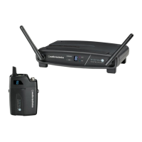
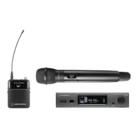
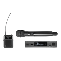
Each professional wireless system includes a receiver and
either a body-pack or handheld transmitter on a specific
crystal-controlled frequency.
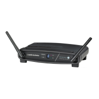
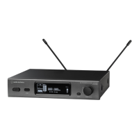
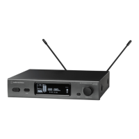
The receiver features true diversity reception. Two antennas
feed two completely independent RF sections on the same
frequency; automatic logic circuitry continuously compares
and selects the superior received signal, providing better
sound quality and reducing the possibility of interference and
dropouts. The receiver is half-width for a standard 19" (1U)
rack mount. Two receivers (on different frequencies) can be
mounted side by side, using an AT8628 joining plate kit.
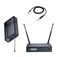
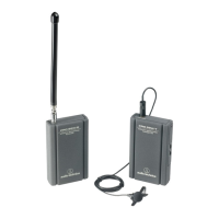
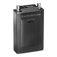
The versatile UniPak
™
body-pack transmitter has both low- and
high-impedance inputs plus a bias connection, for use with
dynamic and electret condenser microphones, as well as Hi-Z
instrument pickups. The UniPak and handheld transmitters use
internal 9-volt batteries and have Off/Standby/On switches and
battery condition indicators.
Please note that in multiple-system applications there must
be a transmitter-receiver combination on a
separate
frequency
for each input desired (only one transmitter for each receiver).
Because the wireless frequencies are in or near VHF TV
frequencies, only certain wireless frequencies are useable in a
particular geographic area. Also, only certain of the available
operating frequencies may be used together. (Frequency
selection information will be found on page 7.)
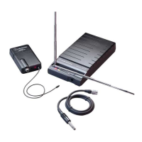
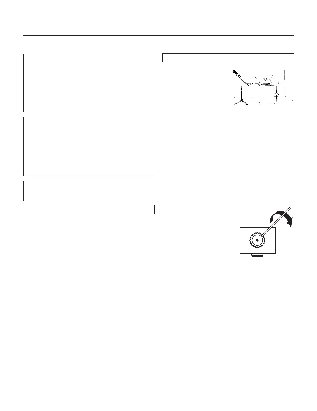
Receiver Installation
Location
For best operation the receiver
should be at least 3 ft. above
the ground and at least 3 ft.
away from a wall or metal
surface to minimize reflections.
The transmitter should be at
least 3 ft. from the receiver,
as shown in Figure A.
Keep antennas away from noise sources such as digital
equipment, motors, automobiles and neon lights, as well
as large metal objects.
Output Connections
There are two audio outputs on the back of the receiver:
balanced (31.6 mV) and unbalanced (100 mV) . Use shielded
audio cable for the connection between the receiver and the
mixer. If the input of the mixer is a
1
⁄
4
" jack, connect a cable
from the
1
⁄
4
" unbalanced audio output on the back of the
receiver to the mixer. If the input of the mixer is an XLR-type
input, connect a cable from the balanced XLR-type audio
output on the back of the receiver to the mixer.
The two isolated audio outputs permit simultaneous feeds to
both unbalanced and balanced inputs. For example, both a
guitar amp and a mixer can be driven by the receiver.
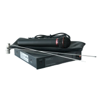
Antennas
Assemble the two whip antennas
to the special connectors
provided. Screw the whips into
the threaded side holes at the
rear of the connector (Fig. B).
Attach the antennas to the
antenna input jacks. The
antennas are normally positioned
in the shape of a “V” (45° from
vertical) for best reception.
Do not try to move the antenna rod after the connector
shell has been tightened down. Always loosen the
connector shell completely before repositioning the rod.
If there is not sufficient space above the receiver and/or if the
receiver is installed in a metal cabinet, the antennas can be
mounted in the threaded holes in the back of the connectors
so the antennas will stick straight out from the back of the
receiver. Use one set of threaded holes or the other; do not
attempt to bend the antenna rods. The optional accessory
ATW-RA1 rack-mount antenna kit brings antenna inputs to the
front of the receiver. When two receivers are mounted side-
by-side in a single 19" rack space, one ATW-RA1 is required
for each receiver.
Power Connections
Connect to a standard 120 volt 60 Hz AC power outlet. If
there is no AC power available, the back panel is equipped
with a jack for an external 12-18 volt DC source. The jack
takes a standard 2.5 mm I.D. coaxial DC power plug, center
negative
. Power from the DC input jack is switched by the
front-panel Power switch.
 Loading...