Information Some actuators are equipped with an additional motor heater. The motor heater
minimises condensation within the motor and improves the start-up behaviour for
extremely low temperatures.
5.2.3 Terminal compartment: close
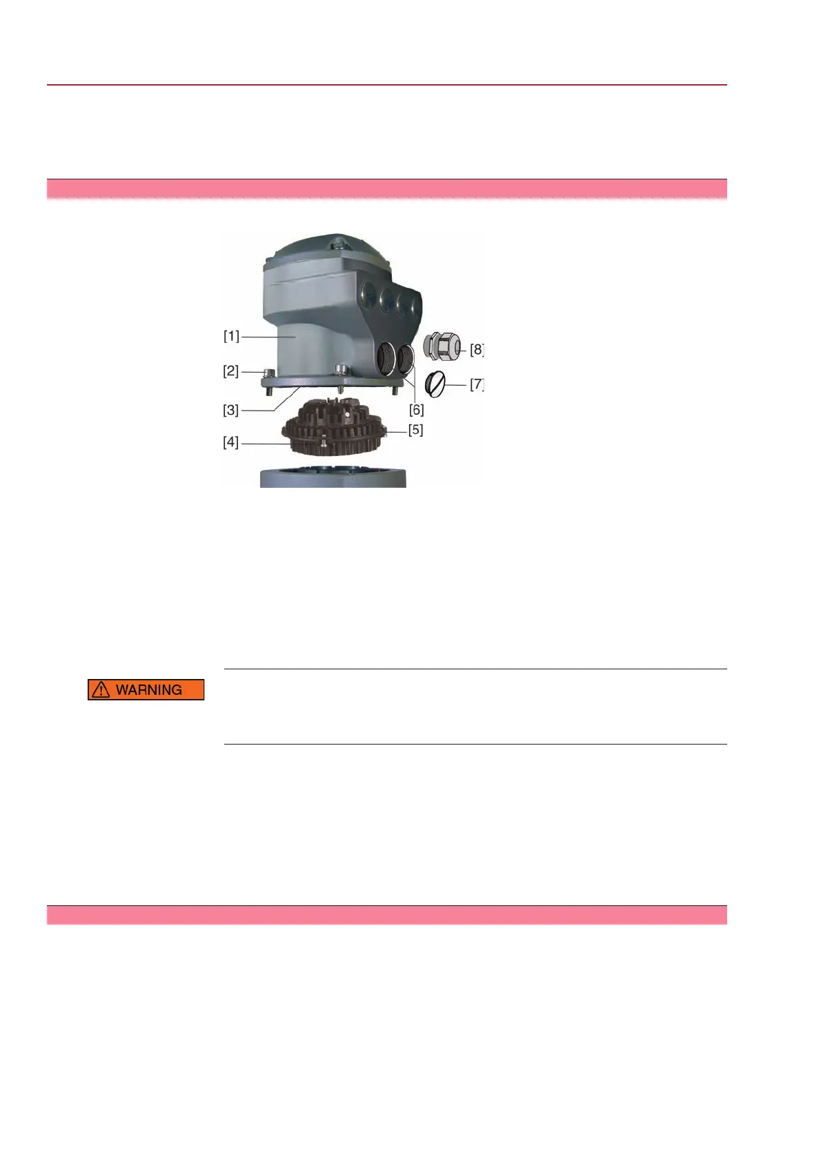
Figure 14: AUMA plug/socket connector SD bus
[1] Connection housing
[2] Screws for connection housing
[3] O-ring
[4] Screws for socket carrier
[5] Socket carrier
[6] Cable entry for mains
[7] Blanking plug
[8] Cable gland (not included in delivery)
Short-circuit due to pinching of cables!
Electric shock and functional failures possible.
→
Carefully fit socket carrier to avoid pinching the cables.
1. Insert the socket carrier [5] into the cover [1] and fasten with screws [4].
2. Clean sealing faces of connection housing [1] and housing.
3. Check whether O-ring [3] is in good condition, replace if damaged.
4. Apply a thin film of non-acidic grease (e.g. petroleum jelly) to the O-ring and
insert it correctly.
5. Fit connection housing [1] and fasten screws [2] evenly crosswise.
6. Fasten cable glands [8] applying the specified torque to ensure the required
enclosure protection.
5.2.4 Bus terminal compartment: open
The AUMA plug/socket connector (SD bus) is equipped with a connection board for
connecting the bus cables. When removing the cover [1] the connection board is
easily accessible.
20
SG 05.1 – SG 12.1/SGR 05.1 – SGR 12.1 Control unit: electromechanic
Electrical connection AC 01.1 Intrusive Modbus RTU
 Loading...


