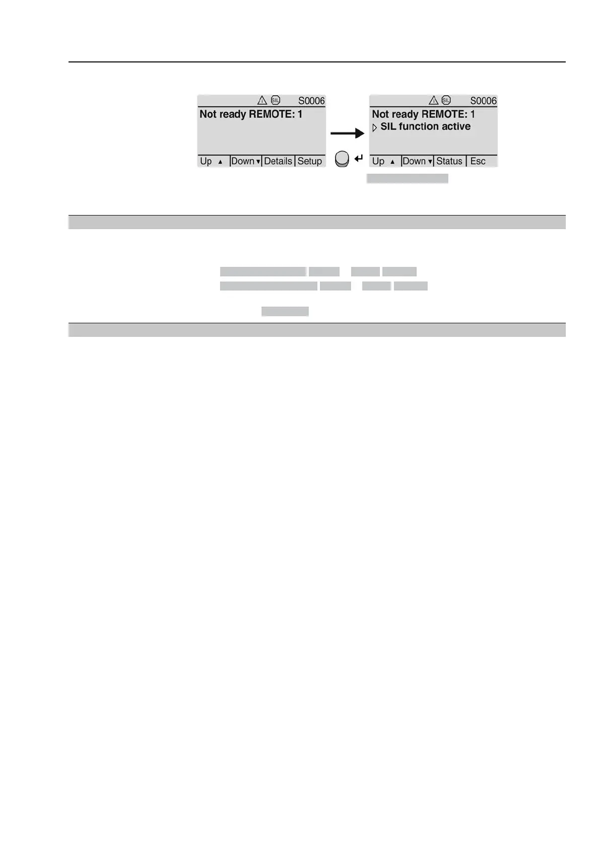
Table 11:
Current consumption of actuator controls
Max. current consumptionMains voltage
±30 %±10 %Permissible variation of the mains voltage
1,200 mA750 mA100 to 120 V AC
750 mA400 mA208 to 240 V AC
400 mA250 mA380 to 500 V AC
400 mA200 mA515 to 690 V AC
Table 12:
Maximum permissible protection
max. protectionRated powerSwitchgear
(switchgear with power class)
1)
16 A (gL/gG)up to 1.5 kWReversing contactor A1
16 A (g/R) I²t<1,500A²sup to 1.5 kWThyristor B1
The AUMA power class (A1, B1, ...) is indicated on the actuator controls name plate1)
Consider the motor starting current (IA) (refer to electrical data sheet) when selecting
the circuit breaker.We recommend tripping characteristics D or K for circuit breakers
in accordance with IEC 60947-2. For controls equipped with thyristors, we recommend
safety fuses instead of circuit breakers. However, the use of circuit breakers is
basically permitted.
We recommend refraining from using residual current devices (RCD). However, if
an RCD is used within the mains, the residual current device must be of type B.
For actuator controls equipped with a heating system and external electronics power
supply, the fuses for the heating system have to be provided by the customer (refer
to wiring diagram F4 ext.)
Table 13:
Fuse for heating system
Designation in wiring diagram = F4 ext.
230 V AC115 V ACExternal power supply
1 A T2 A TFuse
If actuator controls are mounted separately from actuator (actuator controls on wall
bracket): Consider length and cross section of connecting cable when defining the
protection required.
Potential of customer
connections
Refer to Technical data for options of isolated potentials.
Safety standards
Safety measures and safety equipment must comply with the respectively valid
national on site specifications. All externally connected devices shall comply with
the relevant safety standards applicable for the place of installation.
Connecting cables,
cable glands, reducers,
blanking plugs
●
We recommend using connecting cables and connecting terminals according
to rated current (I
N
) (refer to motor name plate or electrical data sheet).
●
For device insulation, appropriate (voltage-proof) cables must be used. Specify
cables for the highest occurring rated voltage.
●
Use connecting cables, cable glands, reducers, blanking plugs with a minimum
temperature range of +80 °C.
●
To avoid contact corrosion, we recommend the use of sealing agents for cable
glands and blanking plugs made of metal.
●
For connecting cables exposed to UV radiation (outdoor installation), use UV
resistant cables.
●
For the connection of position transmitters, screened cables must be used.
23
SQEx 05.2 – SQEx 14.2/SQREx 05.2 – SQREx 14.2 Control unit: electronic (MWG)
ACExC 01.2 Non-Intrusive Profibus DP Electrical connection