7. Signals
7.1. Signals via SIL module
The integrated SIL module signals a SIL fault via an output contact (SIL ready
or SIL failure outputs). Only these signals may be used in a safety-related
system.
For the signal behaviour of the SIL ready/SIL failure outputs, refer to
<Installation> chapter.
Once a SIL fault occurs, the system has to be checked immediately and the
installation has to be put in a safe state, if required.
7.2. SIL - fault signal via the standards actuator controls display (for troubleshooting support)
If the SIL module output contact (SIL ready or SIL failure outputs) signals
a SIL fault, the exact fault can be determined via the indication in the the standards
actuator controls display. For details on all fault indications and warning indications
on the the standards actuator controls display, refer to Manual (Operation and setting)
AUMATIC AC 01.2.
The SIL module output contact serves as collective signal for the faults listed in the
table below.
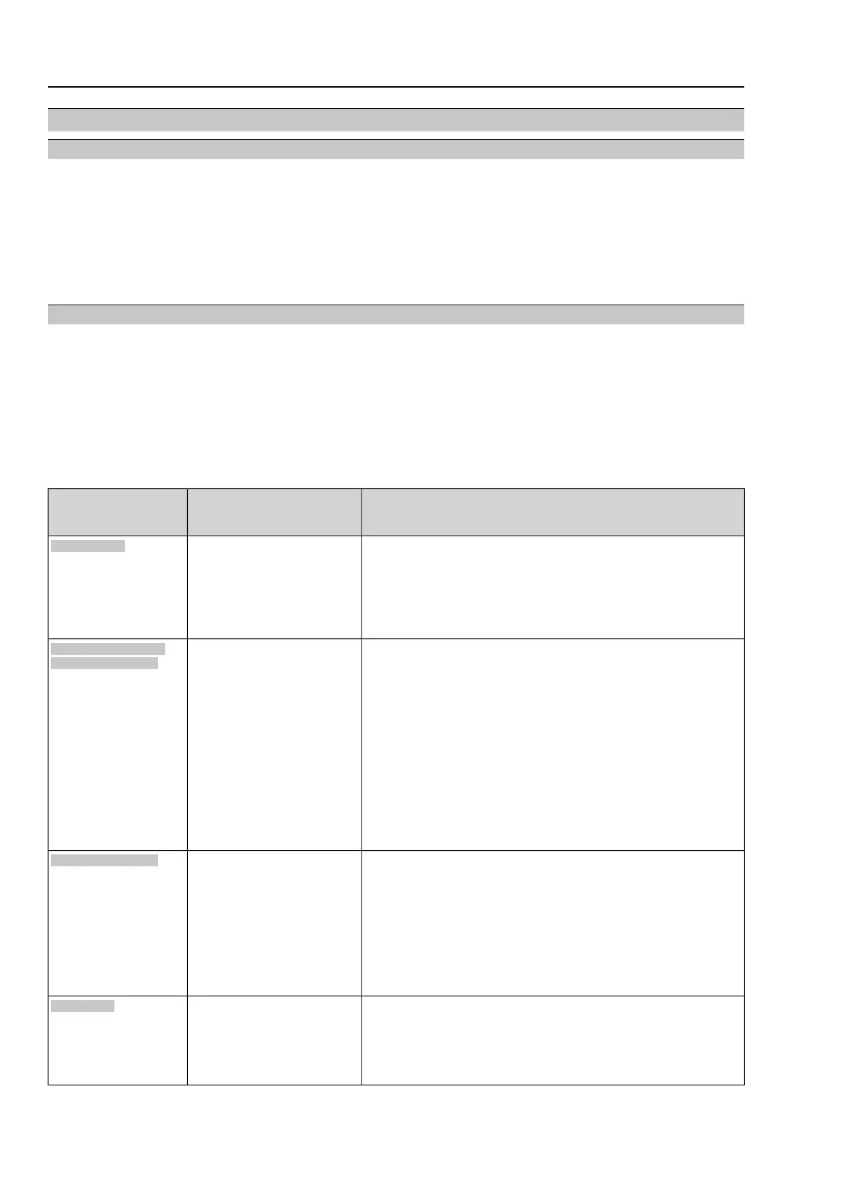
Table 8: Individual signals of SIL fault collective signal
Impact on safety function
→ Remedy
Description/
Cause of the fault
Indication on display
Standard actuator
controls
For version “SIL motor protection” = active:
●
The Safe ESD safety function cannot be executed.
●
If the fault is triggered during safety operation, operation is
stopped.
Remedy
→ Cool down, wait.
Motor protection tripped.
Thermal fault
For “SIL seating” = “Limit seating with overload protection”
configuration:
●
The Safe ESD safety function cannot be executed.
●
If the fault is triggered during safety operation, operation is
stopped.
●
Once the cause for the torque fault has been remedied and the
safety operation is still requested, the safety operation is immedi-
ately continued without manual reset.
Remedy
→ Execute operation command in opposite direction.
→ Verify torque switching setting.
→ Check whether foreign object prevents the valve from closing.
→ Possibly problems with the valve.
Torque fault in directions
CLOSE or OPEN
Torque fault in directions
CLOSE and OPEN (simultan-
eously).
Torque fault CLOSE
Torque fault OPEN
For configurations “SIL seating” = “Limit seating with overload
protection”, “SIL seating” = “Forced limit seating in end posi-
tion”, or “SIL seating” = “Forced torque seating in end position”:
●
The Safe ESD safety function cannot be executed.
●
If the fault is triggered during safety operation, operation is
stopped.
Remedy
→ Verify reduction gearing settings within the actuator.
→ In case of possible defect at the actuator: Contact AUMA service
Current position feedback sig-
nal range is outside the per-
missible range.
Both limit switches (OPEN and
CLOSED) are operated simul-
taneously.
Possibly defect at actuator
mechanics.
Wrn range act.pos.
●
The Safe ESD safety function cannot be executed.
●
The Safe STOP safe function is indirectly executed as the motor
is no longer supplied with power.
Remedy
→ Test/connect phases.
One phase of power supply is
missing.
Controls are not supplied with
mains voltage
Phase fault
24
Part-turn actuators
Signals with AC 01.2-SIL/ACExC 01.2-SIL