Do you have a question about the AUMA SQ 12.2 and is the answer not in the manual?
Provides fundamental safety information, standards, directives, and personnel qualification requirements.
Defines intended use of actuators and lists non-permitted applications.
Details requirements for applications in dust hazardous locations (ZONE 22) under ATEX directive.
Explains safety-relevant procedures and symbols used throughout the manual.
Explains the meaning of references and symbols utilized in the operation instructions.
Describes the information found on the actuator, controls, and motor name plates.
Explains the meaning and components of the type designation on the name plate.
Explains product identification using the order number and documentation access.
Details the structure and meaning of the actuator serial number.
Explains the meaning of the actuator terminal plan designation.
Explains the classification of switchgear according to AUMA power classes.
Provides examples of control indications on the actuator controls name plate.
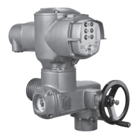
Provides a concise overview of part-turn actuators, controls, and their software.
Provides safety instructions and guidance for transporting actuators, including hovering load warnings.
Details storage requirements, including precautions against corrosion and temperature damage.
Describes protective packaging for transport and recommendations for disposal.
States that the product can be operated in any mounting position with a specific restriction for oil lubricants.
Provides steps for fitting the handwheel onto the actuator input shaft.
Describes how to mount the part-turn actuator to the valve and precautions for paint finish.
Explains valve attachment via coupling, including applications and design.
Details steps for mounting the actuator to the valve using a coupling, including end position recommendations.
Explains how to adjust the mounting position of the local controls.
Provides steps and safety warnings for modifying the local controls mounting position.
Covers warnings, wiring diagrams, permissible networks, and voltage/frequency matching.
Provides recommendations for Modbus wiring, cable specifications, and installation notes.
Details the SD electrical connection using an AUMA plug/socket connector and its technical data.
Describes how to open the terminal compartment for mains connection, including safety warnings.
Provides terminal cross-sections, tightening torques, and instructions for connecting cables, including protective earthing.
Details the steps to close the mains terminal compartment, including safety precautions.
Explains how to open the fieldbus terminal compartment, including safety warnings.
Covers RS-485 connection boards, variants, and cable connection procedures for fieldbus.
Details the steps to close the fieldbus terminal compartment and fastening of cable glands.
Introduces accessories for electrical connections.
Describes the design, application, and precautions for mounting actuator controls on a wall bracket.
Explains the application of a parking frame for safe storage of disconnected plugs or covers.
Describes the DS intermediate frame for double sealing to maintain enclosure protection.
Details the external earth connection using a U-bracket for equipotential compensation.
Explains how to operate the actuator manually for setting or in case of power failure.
Provides steps to engage manual operation, including a warning about motor coupling.
Explains how manual operation is automatically disengaged when the motor restarts.
States that commissioning settings and test run must be performed before motor operation.
Describes how to operate the actuator locally using the push buttons on the actuator controls.
Explains how to operate the actuator remotely and provides a caution regarding unexpected switching on.
Details how to navigate the menu using push buttons for settings and indications.
Explains the groups, IDs, and selection methods for menu navigation.
Describes user levels and the password entry process for parameter modification.
Provides step-by-step instructions for entering a password to access different user levels.
Explains how to change passwords for same or lower access levels.
States that the display is multilingual and provides information on language settings.
Details the steps for changing the display language.
Explains indications during commissioning, including LED test, language selection, and startup menu.
Describes the status bar, navigation support, and valve position indications.
Details valve position feedback and end position indications via symbols.
Explains the torque indication and how to select units.
Describes indications for operation commands like OPEN/CLOSE and setpoint control.
Explains setpoint control indications, including operation command and position setpoint.
Details status indications based on AUMA classification, including warnings.
Groups indications for warnings, remote status, and general faults.
Details status indications according to NAMUR recommendation, starting with 'Out of Specification'.
Groups indications for out-of-specification, function check, maintenance, and failure status.
Explains the arrangement and signification of indication lights on the local controls.
Describes the mechanical position indication using an indicator mark at the cover.
Explains how to read feedback signals via Modbus RTU.
Details status signals via output contacts and their characteristics.
Explains how to assign output contacts (DOUT 1-6) to various signals.
Describes how to set output signals to high active or low active.
Lists requirements for analogue signals and the availability of additional control inputs.
Describes the valve position signal as 0/4 - 20 mA.
Explains how internal end stops limit swing angle and protect the valve.
Provides steps to set the end stop for the CLOSED position.
Details how to set the end stop for the OPEN position.
Explains how to set the type of seating (Limit or Torque) and provides user login information.
Details how to set fieldbus parameters like address, baud rate, parity, and monitoring time.
States that the switch compartment must be opened to perform certain settings.
Explains how to set torque switching for overload protection of the valve.
Describes how limit switching records travel and operates switches at preset positions.
Provides steps to set the end position CLOSED using the black section elements.
Provides steps to set the end position OPEN using the white section elements.
Explains how to set intermediate positions using DUO limit switching.
Details steps to set an intermediate position for the running direction CLOSE.
Details steps to set an intermediate position for the running direction OPEN.
States that test runs should only be performed after all settings are complete.
Describes how to check the direction of rotation on the mechanical position indicator.
Explains how to check if the limit switching is set correctly.
Details how to perform reference operation for position feedback after changing limit settings.
Provides steps to set the mechanical position indicator once optional equipment is set.
Details steps to close the switch compartment, including safety precautions.
Provides technical data and setting elements for the EWG 01.1 electronic position transmitter.
Details how to set the measuring range for the EWG 01.1 transmitter.
Explains how to adjust the current values (0/4/20 mA) for the EWG transmitter.
Explains how to switch LED end position signalling on or off for the EWG transmitter.
Describes the potentiometer used as a travel sensor and its setting elements.
Details how to set the potentiometer for valve position measurement.
Provides technical data and setting elements for the RWG electronic position transmitter.
Details how to set the measuring range for the RWG transmitter.
Lists faults that can occur during commissioning, their causes, and remedies.
Describes how to manually check torque and limit switches.
Explains how faults and warnings are displayed and their influence on operation.
Covers indications for faults, warnings, and out-of-specification conditions from S0001 to Wrn input AIN 1.
Details specific warnings and faults including input signal loss, timing, temperature, and communication issues.
Covers faults related to configuration, motor, phase, mains quality, and potentiometer issues.
Details faults related to input signals, commands, remote/local states, safety functions, and communication.
Provides information about fuses used in the actuator controls and their replacement.
Explains how to replace fuses F1/F2, including safety warnings.
Provides instructions for testing and replacing fuses F3/F4, including checking continuity.
Explains motor protection against overheating using PTC thermistors or thermoswitches.
Lists actions to ensure safe device operation, including visual inspection and torque checks.
Details maintenance tasks, focusing on lubrication schedules and seal replacement.
Explains grease type, change intervals, and seal replacement recommendations.
Provides guidance on the disposal and recycling of devices and their components.
Lists features and functions of part-turn actuators, including type of duty, motors, and voltage.
Covers actuator features, electromechanical unit details, and environmental service conditions.
Details service conditions, corrosion protection, coatings, lifetimes, EU directives, and component data.
Lists features and functions of actuator controls, including power supply and current consumption.
Covers features of actuator controls including fieldbus, voltage, redundancy, FO cables, and local controls.
Details actuator control functions such as Bluetooth, applications, safety features, and monitoring capabilities.
Covers diagnostics, motor protection, electrical connections, Modbus interface settings, and general data.
Details Modbus RTU interface specifics including device support, commands, signals, and communication loss behavior.
Covers enclosure protection, environmental resistance, accessories, and directives relevant to actuator controls.
Shows an exploded view of part-turn actuators and their components.
Shows an exploded view of AC 01.2 actuator controls with SD electrical connection.
Contains the EU Declaration of Conformity and Declaration of Incorporation for the actuators.
| Brand | AUMA |
|---|---|
| Model | SQ 12.2 |
| Category | Controller |
| Language | English |