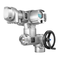
SQ 05.2 – SQ 12.2 / SQEx 05.2 – SQEx 12.2
Switchgear version: Contactors
Safe STOP OPEN or Safe
STOP CLOSE
Safe ESDSafety function
2.26 x 10
–3
2.15 x 10
–3
PFD
avg
T
Proof
= 1 Jahr (1001)
2.32 x 10
–4
2.03 x 10
–4
PFD
avg
T
Proof
= 1 Jahr (1002)
SIL 2 (HFT = 0)
SIL 3 (HFT = 1)
SIL 2 (HFT = 0)
SIL 3 (HFT = 1)
SIL capability
including detected "annunciation" failures (λ
AD
) (failures in diagnostic function)
1)
Table 10: SQ .2/SQEx .2 type range with AC 01.2/ACExC 01.2 actuator controls in
SIL version
SQ 14.2 / SQEx 14.2
Switchgear version: Contactors
Safe STOP OPEN or Safe
STOP CLOSE
Safe ESDSafety function
675 FIT185 FITλ
S
89 FIT856 FITλ
DD
1)
309 FIT263 FITλ
DU
71 %79 %SFF
22 %76 %DC
2.60 x 10
–3
2.58 x 10
–3
PFD
avg
T
Proof
= 1 Jahr (1001)
2.68 x 10
–4
2.48 x 10
–4
PFD
avg
T
Proof
= 1 Jahr (1002)
SIL 2 (HFT = 0)
SIL 3 (HFT = 1)
SIL 2 (HFT = 0)
SIL 3 (HFT = 1)
SIL capability
including detected "annunciation" failures (λ
AD
) (failures in diagnostic function)
1)
Table 11: SQ .2 series with AC 01.2 actuator controls in SIL version
SQ 05.2 – SQ 12.2 / SQR 05.2 – SQR 12.2
Switchgear version:Thyristors
Safe STOP OPEN or Safe
STOP CLOSE
Safe ESDSafety function
626 FIT138 FITλ
S
89 FIT849 FITλ
DD
1)
217 FIT222 FITλ
DU
76 %81 %SFF
29 %79 %DC
1.83 x 10
–3
2.23 x 10
–3
PFD
avg
T
Proof
= 1 Jahr (1001)
1.86 x 10
–4
2.11 x 10
–4
PFD
avg
T
Proof
= 1 Jahr (1002)
SIL 2 (HFT = 0)
SIL 3 (HFT = 1)
SIL 2 (HFT = 0)
SIL 3 (HFT = 1)
SIL capability
including detected "annunciation" failures (λ
AD
) (failures in diagnostic function)
1)
Table 12: SQ .2 series with AC 01.2 actuator controls in SIL version
SQ 14.2 / SQR 14.2
Switchgear version:Thyristors
Safe STOP OPEN or Safe
STOP CLOSE
Safe ESDSafety function
665 FIT138 FITλ
S
89 FIT884 FITλ
DD
1)
257 FIT272 FITλ
DU
74 %78 %SFF
25 %76 %DC
41
Part-turn actuators
with AC 01.2-SIL/ACExC 01.2-SIL Safety-related figures

 Loading...