The stove must be connected to an approved
3” or 4” pellet vent chimney.
14
Before installing, contact your local
building or fire officials about
resrictions and installation inspection
requirements in your area.
Manufacturer and distributor have no
control over the installation of the stove
and assume no responsibility for any
special, incidental or consequential
damages.
DO NOT INSTALL A FLUE
DAMPER IN THE EXHAUST
VENTING SYSTEM OF THIS UNIT!
DO NOT CONNECT THIS UNIT TO
A CHIMNEY FLUE SERVING
ANOTHER APPLIANCE!
ELECTRICAL CONNECTION
The stove is supplied with an approx. 7’ to 8’
long connecting cable. This cable is to be connected
to a normal 110 V, 60 Hz electrical connection. The
average power consumption is approx. 100 watts.
During the ignition process (duration 10 minutes)
approx. 300 watts. The connection cable must be
run so that any contact with hot or sharp-edged
external surfaces on the stove is avoided.
COMBUSTION AIR
Each combustion process requires oxygen or air. As a rule,
the combustion air is taken from the living area in the
house. The air taken from the living area must be reintro-
duced. In modern homes, very tight fitting windows and
doors mean too little air flows into the house for proper
combustion. This situation becomes problematic due to
additional ventilation in the house (e.g. in the kitchen and
bath exhaust fans). Outside air is recommended, but not
required, except in mobile home installation.
The total length of the horizontal vent must not
exceed 30 feet. The “PL” vent exhaust system
must be installed and sealed with 3 screws per
joint. The chimney manufacturer’s installation
procedures must be followed. In addition,
pipe connections, joints, and all pipe seams
within the home should be sealed with high-
temperature silicone sealer, (RTV) aluminum
tape.
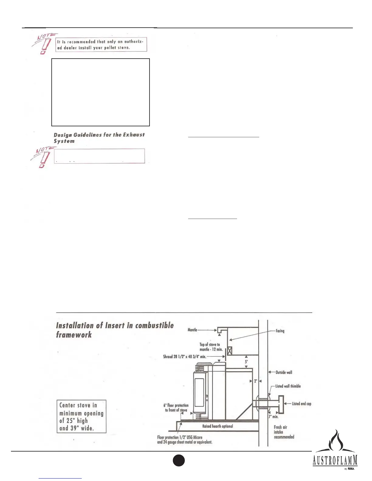
INSTALLATION INSTRUCTIONS INTEGRA II INSERT
29” x 42”
The exit terminal must be located no less
than 60 inches from any opening through
which combustion products could enter the
building (i.e. windows and doors), no less
than 24 inches from an adjacent building,
and no less than seven foot above grade,
when located adjacent to public walkways.
It must be arranged so that exiting flue
gases will not be a hazard to people,
overheat combustible structures, or enter
the building.