english 25
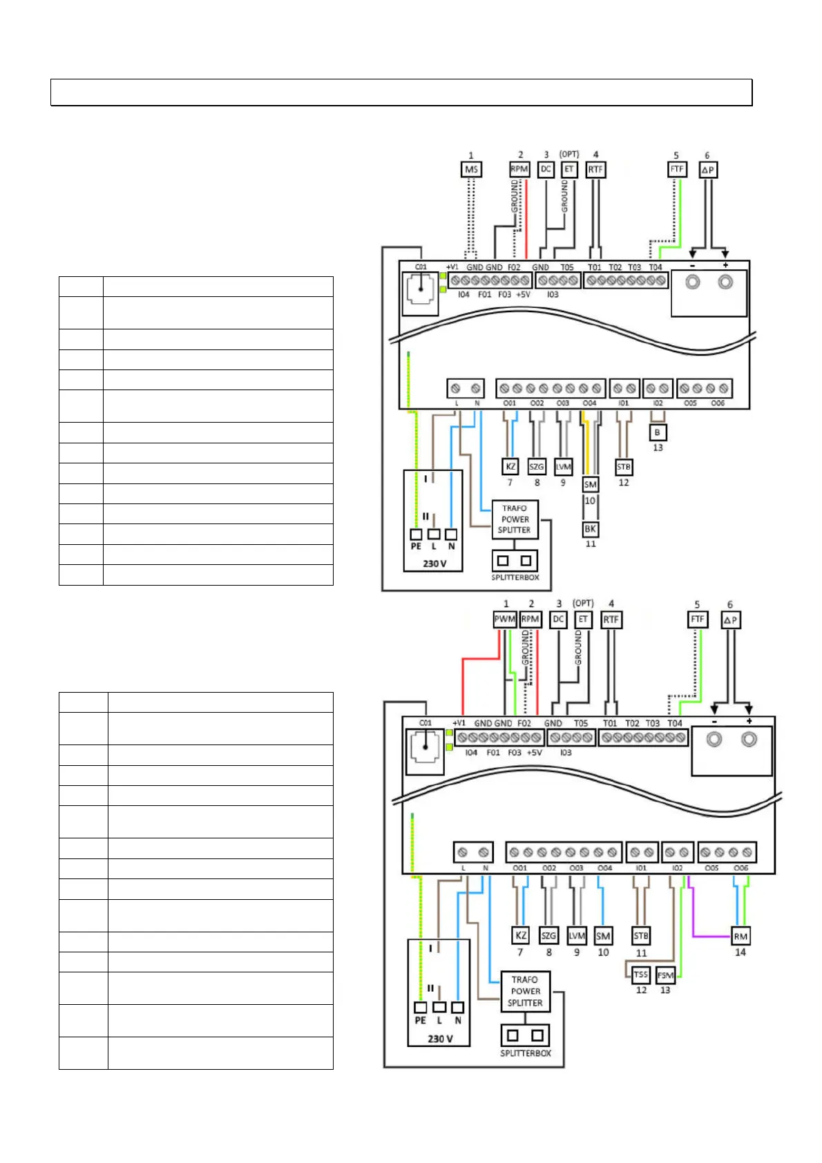
8 Wiring Diagram
Note: Repairs to your pellet stove must only be carried out by approved Austroflamm technicians.
8.1 For models with ON/OFF worm
gear motor
1.
Magnetic switch (hopper lid)
2.
RPM / HAL-IC
Earthing – ID fan
3.
Earthing – DC control side
4.
Room temperature sensor
5.
Firebox temperature sensor
6.
Differential pressure measurement
P1, P2
7.
Ceramic ignition
8.
ID fan
9.
Air distribution module (optional)
10.
ON / OFF – worm gear motor
11.
Blank capacitor
12.
Safety temperature limiter
13.
Jumper “I02“
(OPT)
External thermostat
8.2 For models with a permanently
rotating worm gear motor
1.
Phase converter
2.
RPM / HAL-IC
Earthing – ID fan
3.
Earthing – DC control side
4.
Room temperature sensor
5.
Firebox temperature sensor
6.
Differential pressure measurement
P1, P2
7.
Ceramic ignition
8.
ID fan
9.
Air distribution module (optional)
10.
Current signal - permanently
rotating worm gear motor
11.
Safety temperature limiter
12.
Hopper lid / Safety switch
13.
Grate motor, current release for
worm gear motor
14.
Grate motor
(OPT)
External thermostat