• Select
Diagnostics
from the Main Menu
• Please note: Not all vehicles support topology mapping of all vehicle systems
This quickstart guide applies to the MaxiSys
®
Ultra, MaxiSys
®
MS919 and MaxiSys
®
MS909.
QUICKSTART GUIDE
TOPOLOGY MODULE MAPPING
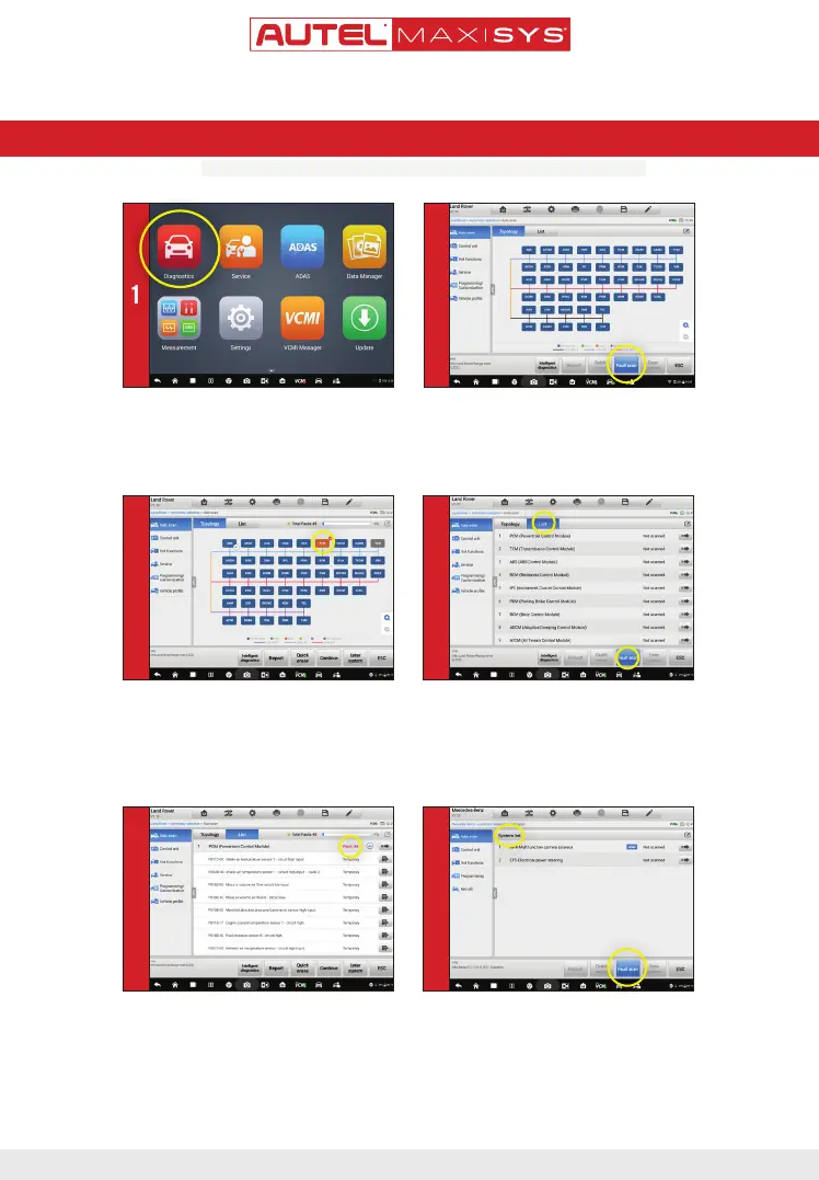
- A topology module map of all available systems
will display after the Auto SCAN. All systems
display in Dark Blue.
• Tap
Fault
scan
at the bottom of the screen to scan
system faults
1 2
ONLY REGISTERED AUTEL TOOLS CAN DOWNLOAD SOFTWARE UPDATES
- A system found to have faults will display in Orange,
with the number of faults detected displayed in the
upper right corner of the system icon.
- A system icon that displays as Green indicates the
system is without faults; A Gray system icon indicates
the system did not respond when scan was attempted.
3
• Tap
List
tab to view all available systems in list
format
- The third column displays Not Scanned indicating the
system has not been scanned.
• Tap
Fault scan
at the bottom of the screen to scan
system for faults
4
• Data Trouble Codes (DTCs) can be viewed directly
after scanning.
• Fault | #: Indicates faults are present; “#”
indicates the number of detected faults.
• Pass | No Fault: Indicates the system was scanned
and no fault was detected
• No Response: Indicates the system was
unresponsive
5
• For vehicles that do not support Topology mapping a
System List will display after the Auto SCAN
• Tap Fault scan at the bottom of the screen to scan
system for faults
• DTCs can be viewed after scanning. Scroll to review
systems.
6
 Loading...