Page 14 (20)
Alarm text Comment
Output circuit overload Short circuit in one of the +24V outputs terminals 41-44.
The outputs are secured with a fuse that makes an automatic
reset. Remove the overload to correct the problem.
Analogue sensor failure [7]
Detailed information on which analog channel that is below
2mA. Here channel 7.
Broken wire [T7 T9] Detailed information on which terminal experiences the
broken wire. Here terminals 7 and 9.
Frontpanel Buttons
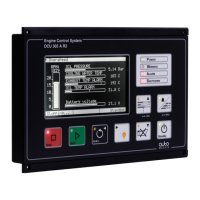
Stop button
Press and hold the red button labelled STOP until stop is activated. When
the red LED by the button is lit, then the stop sequence is activated.
Note: To avoid erroneous operation, the stop button must be pressed 0.5
seconds before stop is activated. Releasing the button before 0.5 seconds
does not activate the stop sequence.
The control unit stops the genset by pulling the stop solenoid.
When the engine speed is below 5rpm, the stop solenoid is released after
7 seconds.
The red LED in the stop button indicates the control unit is pulling the
stop solenoid.
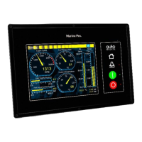
Start button
Manual start is done with the green button labelled START. Press and
hold the button until the engine has started. The starter engine is
discontinued when the engine has started.
A running engine is indicated by the green LED in the Start button and
the text Running in the leftmost status field of the LCD. The rpm-meter
will indicate the engine speed.
Note: The starter engine is excluded when the control unit indicates that
the engine is running.
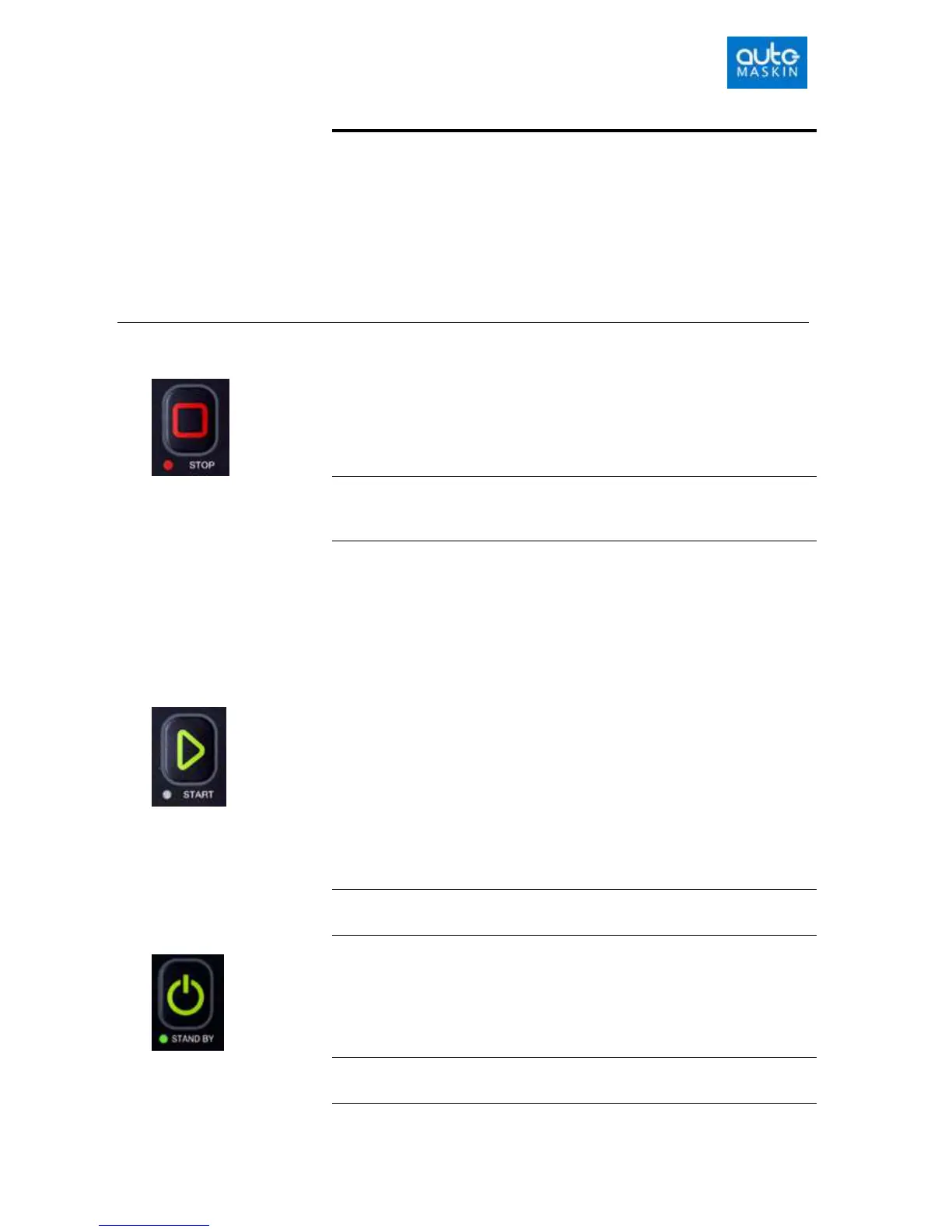
Standby & Manual mode button
The STANDBY button is a toggle button, meaning that for every other
keypress, the unit is set to Standby or Manual.
Note: A green LED in the Standby button indicates that the unit is set to
Standby.

 Loading...