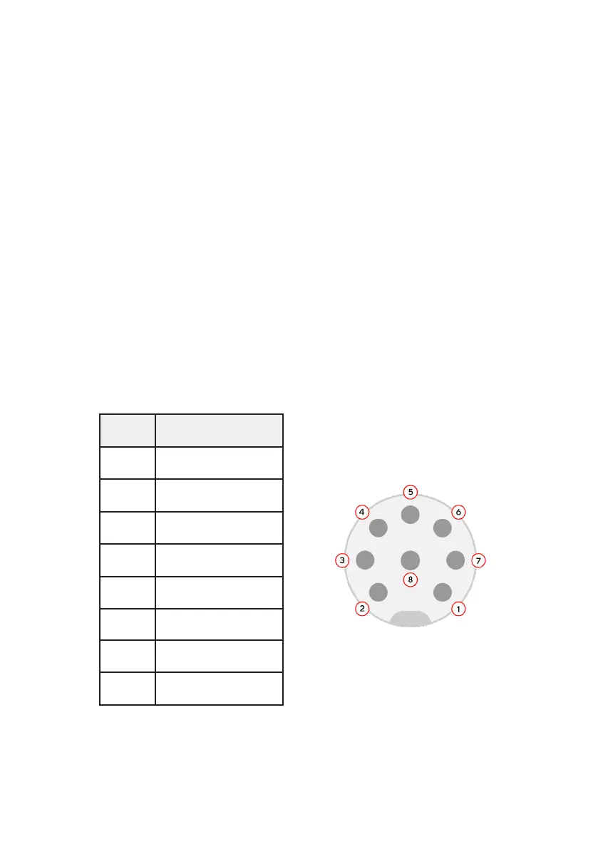
PIN Function
1 Analog Input 1
2 Analog Input 2
3 Digital Input 1
4 Digital Input 2
5 POWER (+24V)
6 Digital Input 1
7 Digital Input 2
8 Tool GND (OV)
The control buttons are each surrounded by an LED ring. The colours of these
rings indicate robot status:
Both lights white = System Idle
Both lights green = Toolpath Running
Backdriving button green, Waypoint button white = Backdriving Mode
Both lights yellow = Fault detected
Tool Port
The tool port uses a circular M8 female connector. It mates with a standard M8
circular male connector, for example the Phoenix Contact 1404178
Available from distributors such as:
Digi-Key 277-12798-ND
Mouser 651-1404178
RS Components 861-0762
The tool port shares a common ground with the base I/O. Ensure all signals con-
nected to the tool port are referenced to the same level. Care must be taken to
control ground paths when measuring analog signals.
24