5
Rev (29-AUG-97) • Module Driver v4.7
© 1995-97 Automated Logic Corporation
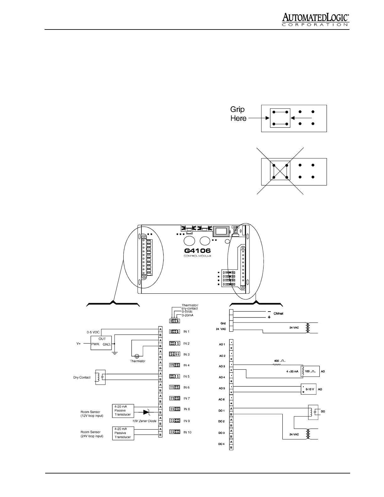
NOTE: In most cases, a 4-20 mA passive transducer does
not require an external power supply (see Figure 6). In
some special cases, when the module’s power is limited, a
4-20 mA passive transducer does require and external
power supply to avoid power consumption from the
module.
Dry Contact: 0.5 mA maximum sense current. Some
current switches that are not true dry contact closures may
not go to zero ohms when the switch is closed. Any
switch which has more than 412 Ohms effective resistance
(0.2V) when closed must have an interposing mechanical
relay when used with G4106 modules.
Procedure
1. Turn the G4106's power switch OFF.
2. Terminate the input wiring to the left termination
strip as shown in Figures 5 and 6.
Figure 5: I/O wiring
Figure 4: Correct input jumper orientation
and gripping method
3. Set the input configuration jumper according to the
type of signal as shown in Figures 5 and 6.
NOTE: The jumper orientation is critical - see
Figure 4. The jumpers are fragile; grip them only
on the sides shown in Figure 4.
4. Turn the G4106's power switch ON.
+
-
+
-
 Loading...