8
Rev (29-AUG-97) • Module Driver v4.7
© 1995-97 Automated Logic Corporation
Figure 8: Example Custom Table
for a Sample Slidepot
(Tested Resistance Entered on the Left)
Digital Outputs
The G4106 provides four digital outputs which are wired
as shown as shown in Figures 5 and 6. These outputs are
described as follows: 24 VAC or VDC maximum, each
configurable as dry contact and as normally open or
normally closed.
Contact Rating: 3 Amp maximum
Procedure
1. Turn the G4106's power switch OFF.
2. Terminate the output wiring to the right termination
strip as shown in Figures 5 and 6.
NOTE: Pilot relays should NOT be powered from
the same transformer which powers the GX boards.
3. Turn the G4106's power switch ON.
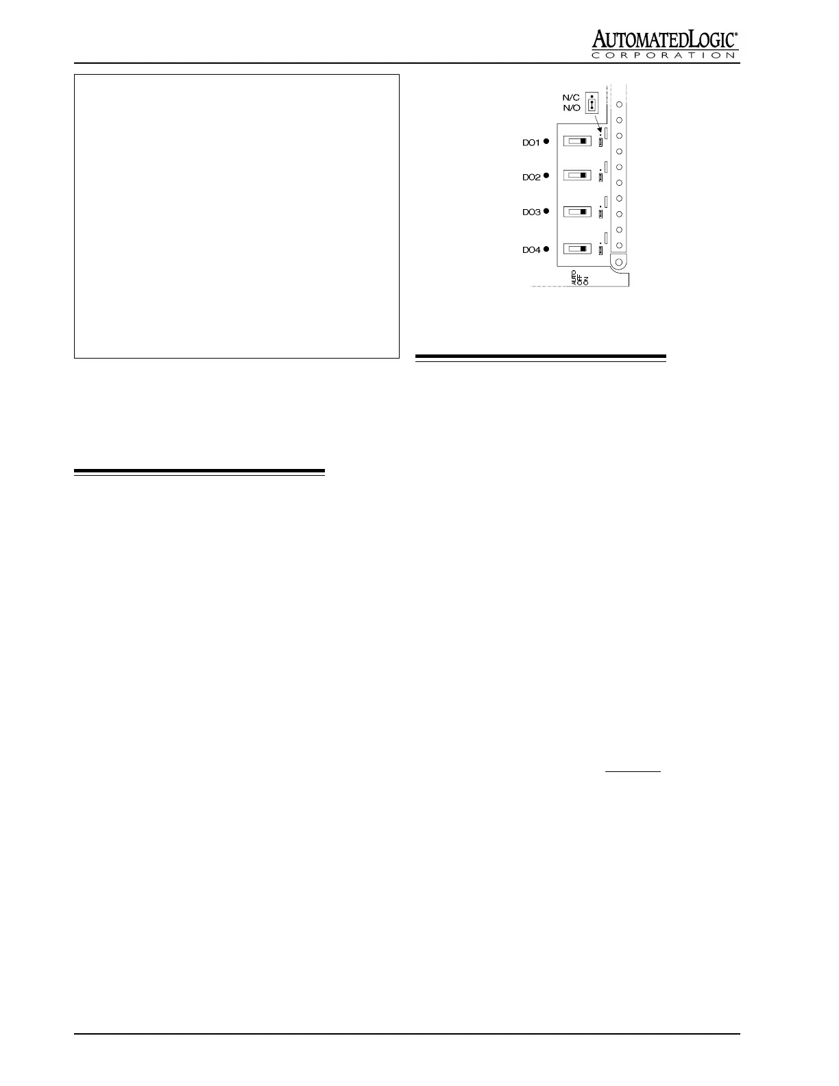
Manual Operation
By setting the HOA switches (see Figure 9), each digital
output can be placed in ON, OFF, or AUTO mode. The
position of the HOA switches may be monitored through
channels 81-88. Channel 81 corresponds to channel 11,
channel 82 corresponds to channel 12, etc. A status of
OFF on these channels indicates the switch is set to AUTO
mode. A status of ON indicates the switch is set to either
ON or OFF mode.
Figure 9: G4106's HOA Switch
Analog Outputs
The G4106 provides six analog outputs. These outputs
are described as follows.
Voltage Mode (0-10 VDC): 1k Ohm minimum load
impedance.
Current Mode (4-20 mA):
While the G4106's analog outputs are designed to output
voltage, it is possible to use these outputs to drive current
mode devices. To do this, wire a 1/2 Watt resistor in series
with the resistive load, as shown in Figures 5 and 6. The
value of the series resistor is determined as follows:
RSERIES = 500 Ohms - RLOAD
NOTE: If your load resistance is greater than 500 ohms,
your full scale output will be less than 20 mA.
Example: We want to drive a 100 Ohm resistive load
with a 0-20 mA signal. To find the value of the series
resistor, subtract the load resistance from 500 Ohms:
RSERIES = 500 Ohms - RLOAD
RSERIES = 500 Ohms - 100 Ohms = 400 Ohms
This example is shown in Figures 5 and 6.
Procedure
1. Turn the G4106's power switch OFF.
2. Terminate the output wiring to the right termination
strip as shown in Figure 3.
3. Turn the G4106's power switch ON.
Input Ohms Input Value
0 x 10 Ohms = -1.00
474 x 10 Ohms = -1.00
607 x 10 Ohms = -0.75
910 x 10 Ohms = -0.50
1210 x 10 Ohms = -0.25
1540 x 10 Ohms = 0.00
1860 x 10 Ohms = 0.25
2150 x 10 Ohms = 0.50
2360 x 10 Ohms = 0.75
2400 x 10 Ohms = 1.00
32767 x 10 Ohms = 1.00
 Loading...