Digital Counter / Timer / Tach User Manual, 1st Ed.
1-800-633-0405
2-118
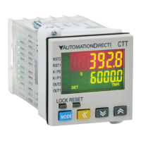
Mode S (
S
) and Mode T(
t
)
When the count present value PV counts up to the count
setting value SV both outputs 1 and 2 will turn ON. The count
PV will continue to increment with each input signal.
The leading edge of a “reset” input signal at RST1 will turn
OFF both outputs, reset the count PV to 0, and prohibit an
input signal from incrementing the count PV. The trailing edge
of the “reset” signal at RST1 enables counting to begin.
The “reset” signal minimum pulse width is set by reset pulse
width parameter (
rtSr
) or DIP Switch 8.
999999
RESET
SV
OUT2
OUT1
PV
DUAL
Input Mode ADDITION
0
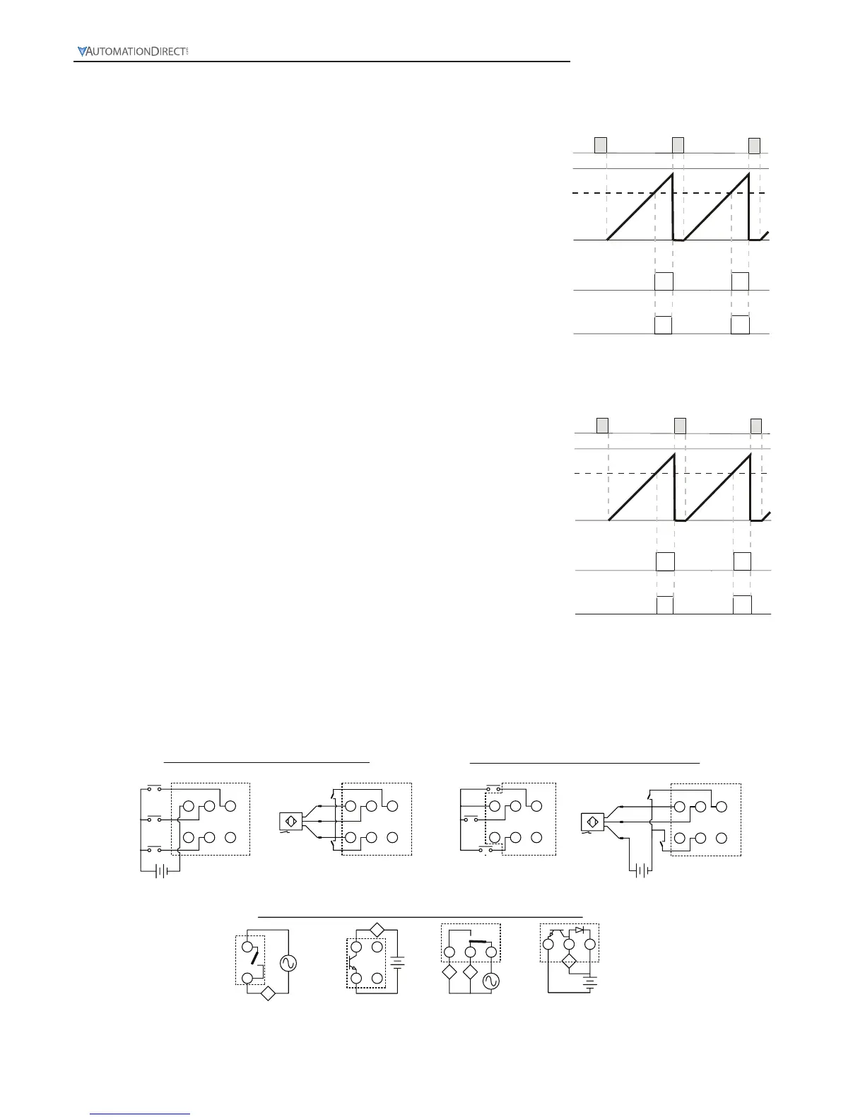
Mode D (
d
)
When the count present value PV counts up to the count setting
value SV both outputs 1 and 2 will turn ON momentarily for
the time set in the output pulse width parameter (
tout2
). The
count PV will continue to increment with each input signal.
The leading edge of a “reset” input signal at RST1 will turn
OFF both outputs, reset the count PV to 0, and prohibit an
input signal from incrementing the count PV. The trailing edge
of the “reset” signal at RST1 enables counting to begin.
The “reset” signal minimum pulse width is set by reset pulse
width parameter (
rtSr
) or DIP Switch 8.
999999
RESET
SV
OUT2
OUT1
PV
DUAL
Input Mode ADDITION
 Loading...