Tach Example 1:
Using PSCALE to convert pulses into engineering units
The PSCALE feature of the CTT is very useful in converting the pulsed signal from an encoder or sensor into some
usable unit of measurement.
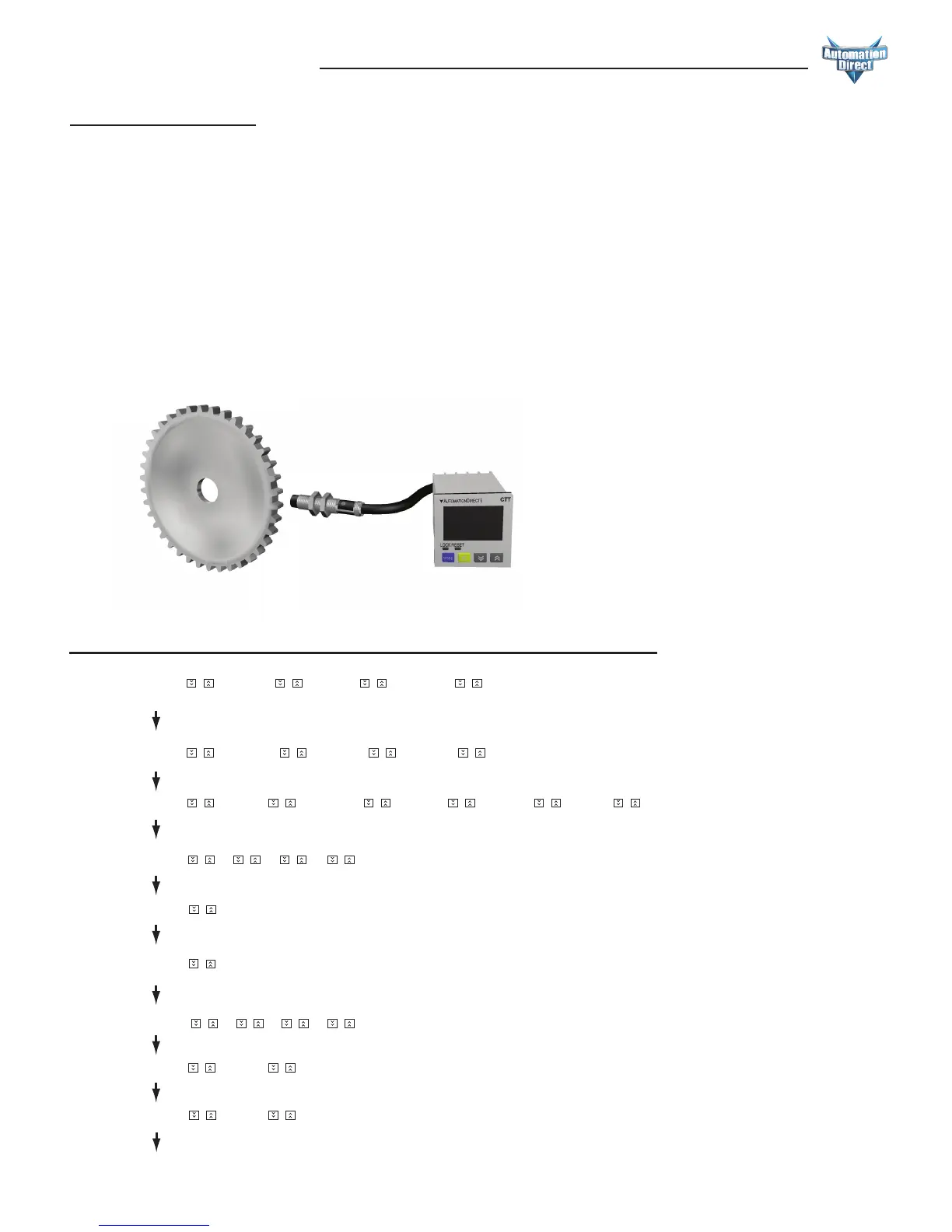
For example if one was to connect a proximity switch to the CTT to monitor the speed of a motor using a sensing gear
there is a simple calculation to convert the pulses from the sensor to Motor RPMs.
Using this formula you can calculate a PSCALE value to change a pulse signal into RPMs. First obtain the pulses per
revolution (ppr) or number of teeth on the sensing gear for example in the illustration below there are 38 teeth on the
gear or 38 ppr. If the gear is coupled directly to the motor this is all that is required to perform the calculation.
PSCALE = 60/ppr or 60/38
PSCALE = 1.579
With the PSCALE set to 1.579 for every 38 input cycles the CTT will display a value of 1.
–FunC
Cont taCh –mixtime
Select rotation speed: Maximum 10Kcps; others 5K, 1K, 200, 30 and 1cps.
Ä
C–Sped
–10k ––5k ––1k –200 ––30
–point
Set up the position of decimal point: 0 (no decimal point), 1 (one digit after decimal point), 2 (two digits after decimal
point), 3 (three digits after decimal point).
0 12 3
psCale
Set up pre-scale value: 1.000 (default 1:1) Range: 0.001 to 99.999
St–taC
Set up the delay time after switching on the power: 0.0 (default). The tachometer will start to run when the set delay
time is due after the power is switched on. Setup range: 0.1 to 99.9 seconds
––00
St–Av6
Set up average value of the input filter: The average value is for making the present value detected by the tachometer
more stable. The setup range is 0 to 3 (1 = 2 data, 2 = 4 data, 3 = 8 data). For example, if you select “3”, the system will
average the 8 present values from the tachometer to make the present value displayed on the screen more stable.
–rtsr
Set up minimum width of reset signal: Default = 20ms; 1ms is also selectable.
––20 –––1
Select output modes: There are 4 output modes, 2Lo1Lo, 2Lo1Hi, 2Hi1Lo, and 2Hi1Hi, For example, when you select
2Hi1Lo, and assume the first set value is 100 (2Hi) and the second 50 (1Lo), the output value of the tachometer will be
below 100 (2Hi) and above 50 (1Lo) and CTT will not perform an output. If the set value exceeds the range, CTT will
perform an output.
taotmd
2Lo1Lo 2Lo1Hi 2Hi1Lo 2Hi1Hi
–––1
1000
0 12 3
InptlC
–npn –pnp
Select input signal types: NPN and PNP.
or
or
or
or
or
or
or
or
or or
or or
or
or
or or or or or
or or
ororor
or
or
or or
Ä
Ä
Ä
Ä
Ä
Ä
Ä
Ä
www.automationdirect.com
6-7
Digital Counter / Timer / Tach User Manual, 1st Ed.
Keypad set up of the parameters in the Tachometer:
 Loading...