Digital Counter / Timer / Tach User Manual, 1st Ed.
1-800-633-0405
3-20
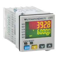
Repeat Cycle 2 (
rCy2
)
With power applied to the CTT, the leading edge of
the input signal at START will begin the timing period
timing up or down based on parameter (
t modE
). At
the end of the timing period, the timing period will
reset and repeat automatically.
Both outputs will turn ON at the beginning of the first
timing period and turn OFF when the timing period
reaches time period setting SV2. The outputs will turn
ON again when the time period reaches time period
setting SV1.
The trailing edge of the “start” signal has no effect on
the outputs or timing period.
The leading edge of a “reset” input signal at RST1 will
turn OFF the outputs and reset the timing period. The
“reset” signal minimum pulse width is set by reset pulse
width parameter (
rtSr
). The leading edge of a new
“start” signal is necessary to restart the cycle.
The leading edge of a “pause” input signal at GATE
will pause the timing period after it has been started.
The timing period will continue after the trailing edge
of the external switch “pause” (Gate) signal.
When power is removed, both outputs will turn OFF
and the timing period will be reset.
CTT Timer
Repeat Cycle 2
Power signal
Start signal
Pause signal
Reset
 Loading...