109
321
1514
10
15
321
876
131211
876
131211
CP2/
GATE (Pause)
CP2/
GATE (Pause)
CP2/
GATE (Pause)
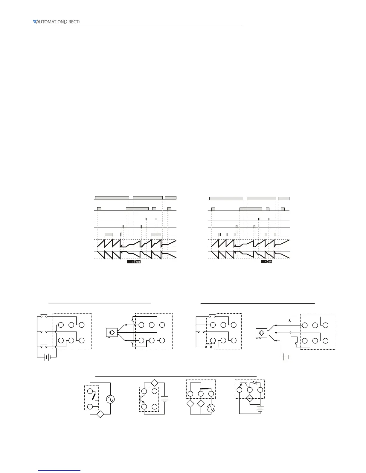
Repeat Cycle HOLD (
rCyH
)
With power applied to the CTT, the leading edge of the input signal at START will begin the timing period setting value SV (timing
up or down based on parameter (
t modE
). At the end of the timing period, the timing period will reset and repeat automatically.
If the output pulse width parameter (
tout1
) is set to 0, both outputs will turn ON at the end of the first timing period, turn OFF
at the end of the next timing period, turn ON at the end of the next timing period, etc.
If the output pulse width parameter (
tout1
) is set to >0.00, both outputs will turn ON momentarily for the time set in the output
pulse width parameter (
tout1
) at the beginning of the each timing period.
The trailing edge of the “start” signal has no effect on the outputs or timing period.
The leading edge of a “reset” input signal at RST1 will turn OFF the outputs and reset the timing period. The “reset” signal
minimum pulse width is set by reset pulse width parameter (
rtSr
). The leading edge of a new “start” signal is necessary to restart
the cycle.
The leading edge of a “pause” input signal at GATE will pause the timing period after it has been started. The timing period will
continue after the trailing edge of the external switch “pause” (Gate) signal.
When power is removed, both outputs will turn OFF. The last state of the outputs and the last value of the current timing period
will be “stored” in Eeprom when power is removed. When power is reapplied the outputs will return to their last state and timing
will resume from the last value of the timing period by the leading edge of a new “start” signal.
CTT Timer
Repeat Cycle Hold
Power signal
Start signal
Pause signal
Reset
Output signal
Up
Down
SV
SV
0
0
Repeat Cycle Hold
Timer output set as 0
Power signal
Start signal
Pause signal
Reset
Output signal
Up
Down
SV
SV
0
0
RCYH timer output not set as 0
tt
t
 Loading...