Digital Counter / Timer / Tach User Manual, 1st Ed.
1-800-633-0405
6-8
Tach Example 2:
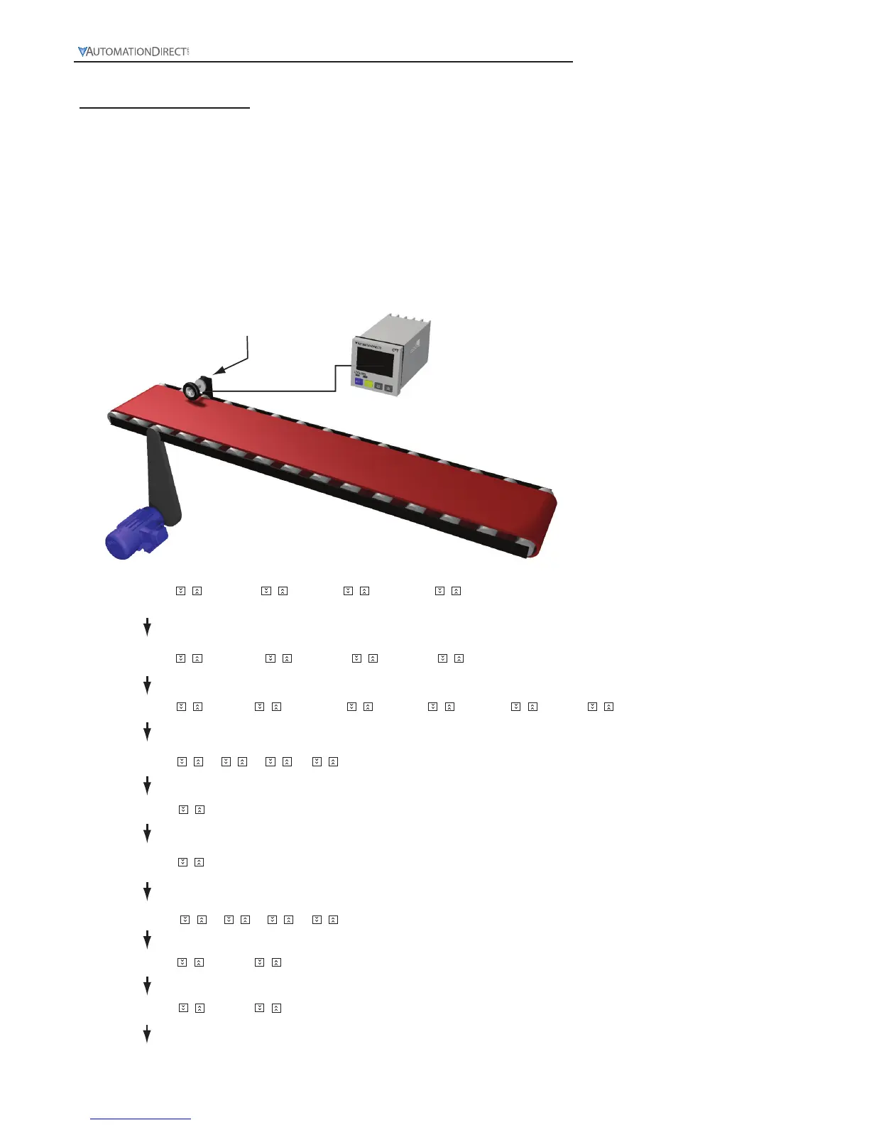
Convert an encoder signal into surface speed of a conveyor.
In order to monitor the speed of a part deliver conveyor belt an encoder with a surface contact measuring wheel is
attached to a conveyor where wheel will be in constant contact with the conveyor. Then the PSCALE is set to convert
the pulse signal of the encoder into feet/per/minute. Two variables are required, the Encoders pulses per revolution
(ppr) the diameter of the measuring wheel. For example when using an AutomationDirect TRD‐N100‐RZWD encoder
which has 100 ppr in conjunction with a measuring wheel that is 6 inch in diameter the calculation would be as follows:
Wheel Diameter * π or 6*3.1416 or 18.85” in circumference. 1 revolution of the wheel translates to
18.85” of linear motion.
PSCALE = wheel circumference / ppr or 18.85/100 = 0.1885 PSCALE.
Measuring Wheel
–FunC Cont taCh –miytime
Select rotation speed: Maximum 10Kcps; others 5K, 1K, 200, 30 and 1cps.
Ä
C–Sped –10k ––5k ––1k –200 ––30
–point
Set up the position of decimal point: 0 (no decimal point), 1 (one digit after decimal point), 2 (two digits after decimal
point), 3 (three digits after decimal point).
0 12 3
psCale
Set up pre-scale value: 1.000 (default 1:1) Range: 0.001 to 99.999
St–taC
Set up the delay time after switching on the power: 0.0 (default). The tachometer will start to run when the set delay
time is due after the power is switched on. Setup range: 0.1 to 99.9 seconds
––00
St–Av6
Set up average value of the input filter: The average value is for making the present value detected by the tachometer
more stable. The setup range is 0 to 3 (1 = 2 data, 2 = 4 data, 3 = 8 data). For example, if you select 3”, the system will
averagethe 8 present values from the tachometer to make the present value displayed on the screen more stable.
–rtsr
Set up minimum width of reset signal: Default = 20ms; 1ms is also selectable.
––20 –––1
Select output modes: There are 4 output modes, 2Lo1Lo, 2Lo1Hi, 2Hi1Lo, and 2Hi1Hi, For example, when you select
1Hi1Lo, and assume the first set value is 100 (2Hi) and the second 50 (1Lo), the output value of the tachometer will be
below 100 (2Hi) and above 50 (1Lo) and CTA will not perform an output. If the set value exceeds the range, CTT will
perform an output.
taotmd 2Lo1Lo 2Lo1Hi 2Hi1Lo 2Hi1Hi
–––1
1000
0 12 3
InptlC –npn –pnp
 Loading...