Digital Counter / Timer / Tach User Manual, 1st Ed.
1-800-633-0405
5-4
2Hi1Hi
When the measured present value PV is greater than
or equal to the set value SV1 Output 1 will turn ON.
When the measured PV is less than SV1 Output 1 will
turn OFF.
When the measured present value PV is greater than
or equal to the set value SV2 Output 2 will turn ON.
When the measured PV is less than SV2 Output 2 will
turn OFF.
OUT2 set value
Measurement value
OUT1 set value
OUT1
OUT2
(HI-HI)
Measurement value
OUT1 set value : OUT1 ON
Measurement value
OUT2 set value : OUT2 ON
Output Mode - Table 2
Switch 3 Switch 4 Output Mode
OFF OFF
Lo-Lo
ON OFF
Lo-Hi
OFF ON
Hi-Lo
ON ON
Hi-Hi
Dip Switch Settings - Table 1
Switch Function Off On
1 Dip switch Disabled Enabled
2 N/A N/A N/A
3
Output
mode
See Output Mode Table
- Table 2
4
5
Counting
Speed
30Hz 10KHz
6 N/A N/A N/A
7 Input type NPN PNP
8
Reset signal
pulse width
20 ms 1 ms
0V CP1
+12V RST1
RST2/
START
Outputs
Load
Load
OUT1
NPN/
SINKING
OUT2
SPDT
Load
OUT1
SPST
Load
OUT2
NPN/
SINKING
Load
+VDC
0VDC
+VDC
0VDC
Reset
0V CP1
+12V RST1
RST2/
START
Reset
+VDC 0VDC
876
131211
Tachometer
Wiring
Examples
109
321
1514
10
15
321
876
131211
CP2/
GATE (Pause)
CP2/
GATE (Pause)
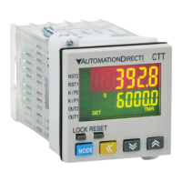
DIP Switch Set Up of the CTT Parameters:
Click on the above thumbnail or go to
https://www.automationdirect.com/VID-RL-0006
for a short Tachometer demo video.
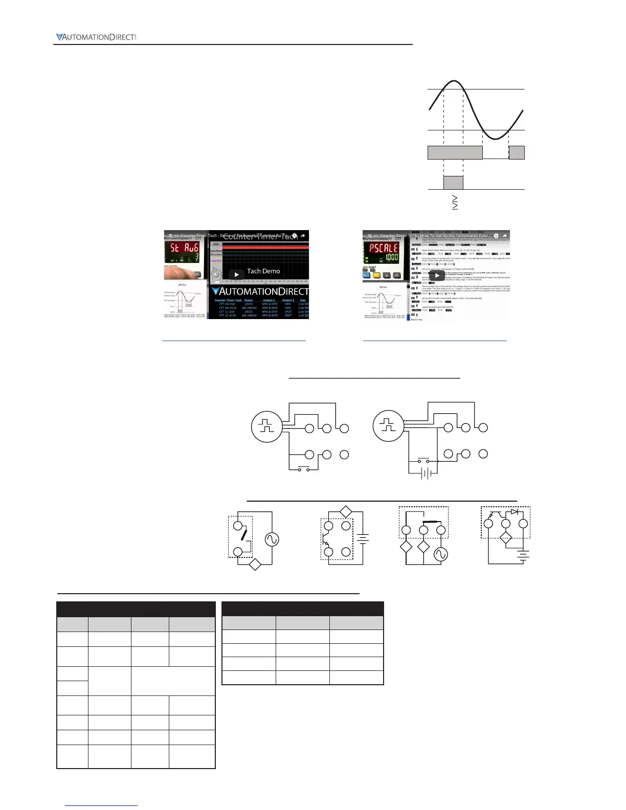
Click on the above thumbnail or go to
https://www.automationdirect.com/VID-RL-0005
for a Tachometer Set-up video.
 Loading...