I-52
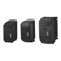
SPC1 Series
F.G.
F.G.
+5V
+5V
IN
IN
IN
+
24VDC
-
IN
GND
GND
②
①
(min.)
(max.)
③
1
2
3
4
5
6
7
9
8
11
10
12
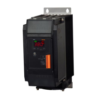
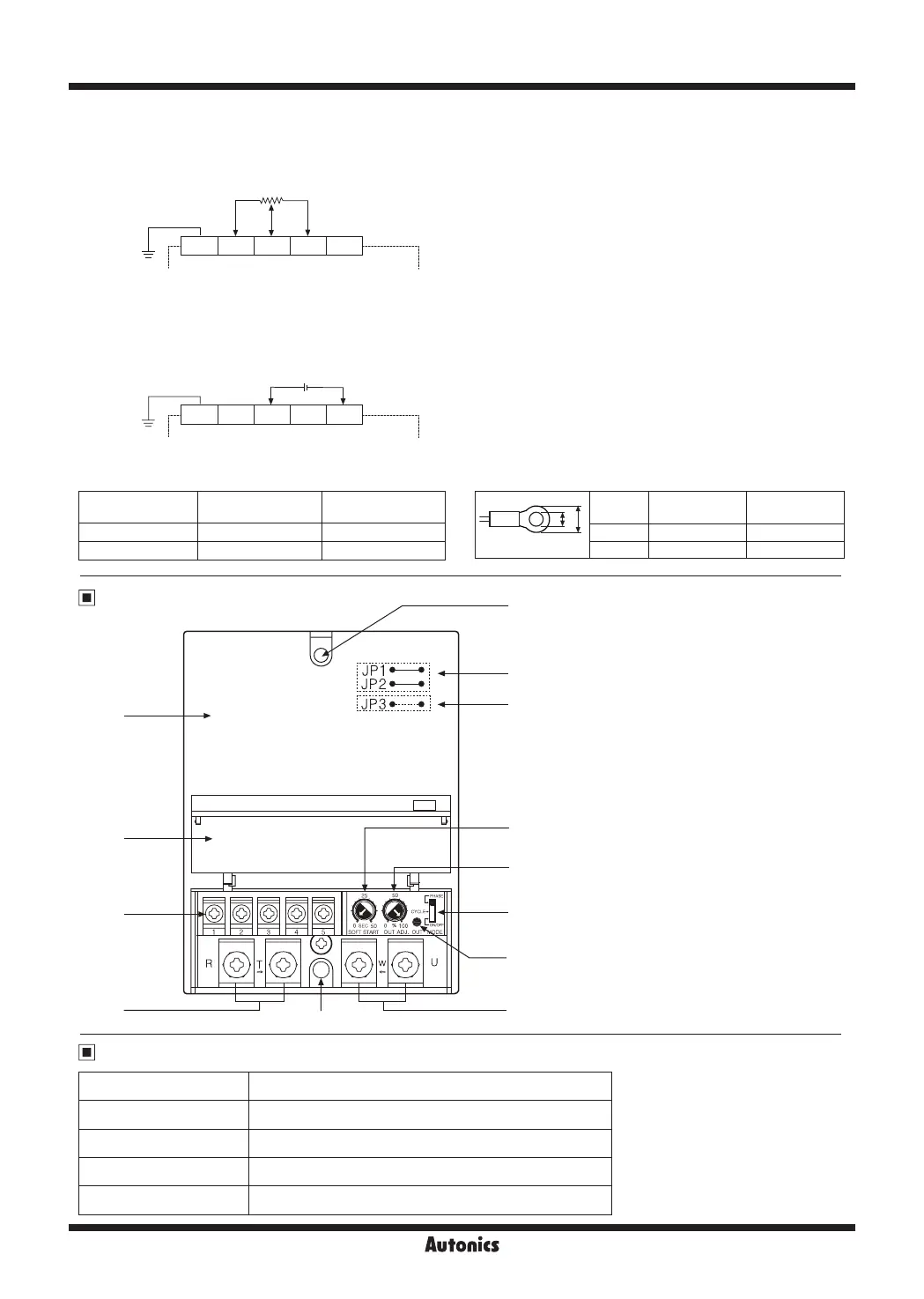
1. Case
2. Terminal block cover
3. Terminal block for control input
4. Terminal block of the power
5. Terminal block for load connection
6. Output indicator (OUT)
7. Control method selection switch
8. SOFT START setting adjuster
9. Output limit setting adjuster
10. Selection jumper of control period
11. Selection jumper of control mode
12. Panel mounting hole
(bolt size: M4×50mm)
※
10, 11 are placed on the inner PCB of the
product.
12
1 2 3 4 5
1 2 3 4 5
External adjuster 1kΩ
※
This function must not be used in ON/OFF control method.
※
It is available for all control methods.
OUT ADJ and SOFT START functions are not available
in ON/OFF control method.
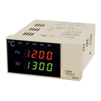
4) External adjuster control input
After power is applied, connecting the external adjuster 1
㏀
to
②, ③
and
⑤
terminals and turning adjuster control from 0%
to 100%.
It is available to control as OUT ADJ, adjuster for the above 1), 2), 3) and set at 100% when it is not used.
5) External 24VDC control input
It can be used with external 24VDC voltage as below.
It is available to control of ON/OFF, outputs 100% for applying 24VDC and 0% for applying 0VDC.
Unit Description
Factory Default
Control method Phase control
Control mode Phase equal division type according to control input
Control cycle period 0.5 sec (JP1, JP2 short)
SOFT START setting 0 sec
OUT ADJ. setting 100%
※
Tighten the terminal screw with the below tightening torque.
Terminal type
Signal input
(control input)
Output and power
Screw M3.5 M5
Tightening torque 0.6 to 1.2N
.
m 1.5 to 2.2N
.
m
a b
<Round>
Terminal
type
Signal input
(control input)
Output and
power
a Min. 3.5mm Min. 5mm
b Max. 7.0mm Max. 12mm
※
Use terminals of size specied below.

 Loading...