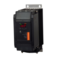
I-55
Single-Phase, Power Controller
(A)
Photoelectric
Sensors
(B)
Fiber
Optic
Sensors
(C)
Door/Area
Sensors
(D)
Proximity
Sensors
(E)
Pressure
Sensors
(F)
Rotary
Encoders
(G)
Connectors/
Connector Cables/
Sensor Distribution
Boxes/Sockets
(H)
Temperature
Controllers
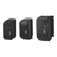
(I)
SSRs / Power
Controllers
(J)
Counters
(K)
Timers
(L)
Panel
Meters
(M)
Tacho /
Speed / Pulse
Meters
(N)
Display
Units
(O)
Sensor
Controllers
(P)
Switching
Mode Power
Supplies
(Q)
Stepper Motors
& Drivers
& Controllers
(R)
Graphic/
Logic
Panels
(S)
Field
Network
Devices
(T)
Software
Proper Usage
Temperature Derating Curve
1. Follow instructions in 'Cautions during Use'. Otherwise, it may cause unexpected accidents.
2. Use the product, after 3 sec of supplying power.
3. Before use, set the mode and function according to the specication.
Especially, be cautious that the product does not operate when OUT ADJ. is set to 0%.
Since mode/parameter can not be changed during operation, set the mode and function after turning off the power.
4. To ensure the reliability of the product, install the product on the panel or metal surface vertically to the ground.
5. Install the unit in the well ventilated place.
6. While supplying power to the load or right after turning off the power of the load, do not touch the body and heat sink.
Failure to follow this instruction may result in a burn due to the high temperature.
7. Install a power switch or circuit breaker in the easily accessible place for supplying or disconnecting the power.
8. Do not wire to terminals which are not used.
9. The rapid fuse must be connected between R terminal and the power source.
10. Do not use near the equipment which generates strong magnetic force or high frequency noise.
11. This unit may be used in the following environments.
①
Indoors (in the environment condition rated in 'Specications')
②
Altitude max. 2,000m
③
Pollution degree 2
④
Installation category III
E.g. 1) When controlling by limiting the power at ON/OFF
in phase control and cycle control method.
For example, if it needs to control 80% output when
it is ON, 24% output when it is OFF, please keep
below.
Firstly set OUT ADJ. as 80% and connect external
adjuster and external relay contact switch as the
gure then set external adjuster as 30%.
● When the External contact signal is ON
: 100% (contact input)×80% (OUT ADJ.)=80%
● When the External contact signal is OFF
: 30% (adjuster input)×80% (OUT ADJ.)=24%
E.g. 2) This is how to control 0 to 100% without
external adjuster in phase control and cycle
control method.
It is possible to control 0 to 100% by turning
OUT ADJ. in state of connecting terminal 2
and terminal 3.
Cautions during use
Applications
SPC1-35-E SPC1-50-E
<Control input terminal connection>
F.G. +5V IN IN GND
1 2 3 4 5
<Control input terminal connection>
F.G. +5V IN IN GND
1 2 3 4 5
External
adjuster 1kΩ
Load current [A]
Ambient temperature [
℃
]
0
40
30
50
20
10
0
10 20 30 40 50
Load current [A]
Ambient temperature [
℃
]
0
40
30
50
20
10
0
10 20 30 40 50
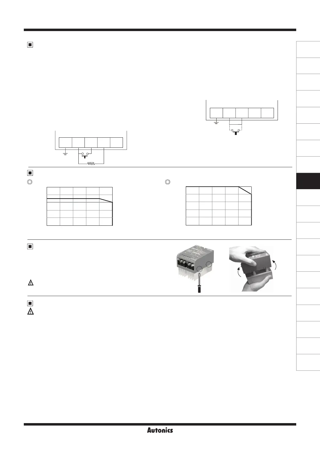
Remove of Case
When using the tool, be careful not to injure yourself.
After disconnecting all power sources supplied to the product,
remove the case.
Push the Joint part (4 points) on the right and left side of the case
with the at head screwdriver, and disassemble the case.

 Loading...