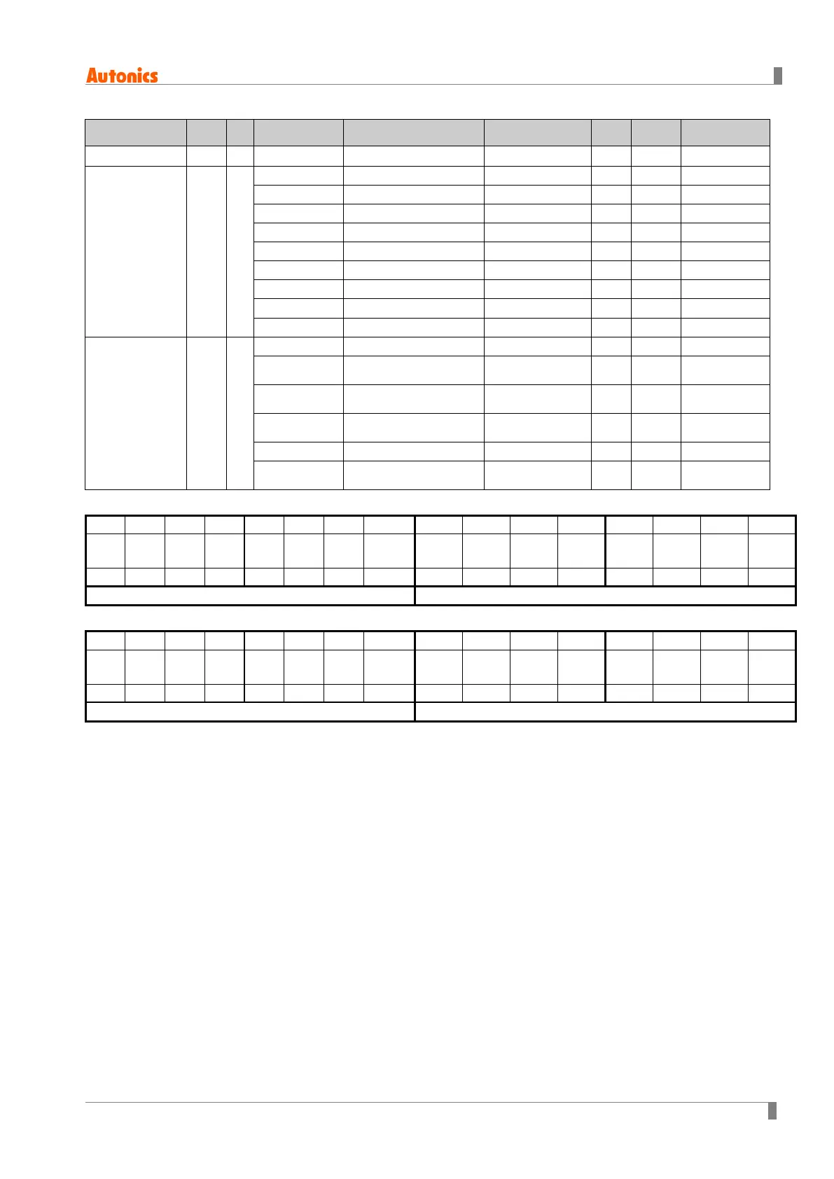
2 Modbus Mapping Table
© Copyright Reserved Autonics Co., Ltd. 23
No(Address) Func R/W Parameter Description Setting Range Unit
Note
301011 (03F2) 04 R
FRQ
Power supply frequency
0.0 to 99.9
Hz -
301012 (03F3)
※
1
04 R
Operation indicator
0: OFF
1 : ON
- - Bit 0
MAN LAMP
Manual control indicator
0: OFF
1 : ON
- - Bit 1
ALM LAMP
Alarm output indicator
0: OFF
1 : ON
- - Bit 2
OUT LAMP
Control output indicator
0: OFF
1 : ON
- - Bit 3
V LAMP
Unit indicator
0: OFF
1 : ON
- - Bit 4
A LAMP
Unit indicator
0: OFF
1 : ON
- - Bit 5
RUN D/I
RUN contact input status
0: OFF
1 : ON
- - Bit 6
AUTO contact input status
0: OFF
1 : ON
- - Bit 7
RESET D/I
RESET contact input status
0: OFF
1 : ON
- - Bit 8
301013 (03F4)
※
2
04 R
Fuse Alarm
Fuse break alarm
0: OFF
1 : ON
- - Bit 0
Overcurrent alarm
0: OFF
1 : ON
- - Bit 1
Overvoltage alarm
0: OFF
1 : ON
- - Bit 2
Heatsink overheat alarm
0: OFF
1 : ON
- - Bit 3
SCR error alarm
0: OFF
1 : ON
- - Bit 4
Heater break alarm
0: OFF
1 : ON
- - Bit 5
※1. 301012 (03F3) address data organization
- - - - - - - RESET
AUTO
RUN
A
indicator
V
indicator
OUT
indicator
ALM
indicator
MAN
indicator
RUN
indicator
※2. 301013 (03F4) address data organization
- - - - - - - - - - Heater
SCR
Heatsink
overheat
Over-
Over-
Fuse

 Loading...