Autostacker™ Parking Lift 56 P/N 5900248 — Rev. B — May 2021
Installing the Control Stands
The Control Stand holds the Controls to operate a Lift in your setup; each Lift has its own Control
Stand. The Control Stand can be placed at the Front or Rear of the Lift, although the installation for
either orientation is different. Those procedures are described here.
NOTICE The following steps explain how to
install
, but not make the connections to, the
Controls for each Lift. An Electrician is
not
needed to install the Controls, only to
connect them to the Power Unit.
⚠ DANGER Do not connect the wires to the Power Unit at this point; that task is for an
Electrician.
All wiring connections to the Power Unit must be
performed by a licensed, certified Electrician
.
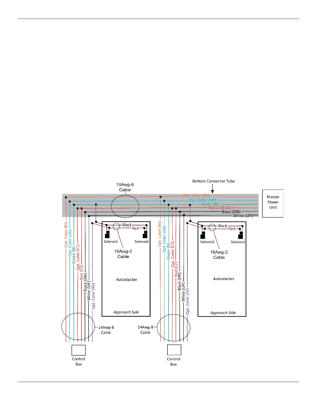
Each Control Stand requires three Electrical Cables:
• #14Awg – 6 wires; one end of the Cable goes to the Power Unit, and the other end goes
through the Bottom Connector Tube, interlinking all of the Lifts in your configuration.
• #14Awg – 8 wires; one end of the Cable connects the Controls on each Stand, the other end
connects to the 14Awg-6 Cable in the Bottom Connector.
• #16Awg – 2 wires. Connects the two Solenoids on each Lift, and the other end goes to the
Controls on the Control Stand.
The following graphic shows the various connections to make to the Control Stands.
Not drawn to scale. Some components are missing or exaggerated for easier understanding.