Autostacker™ Parking Lift 58 P/N 5900248 — Rev. B — May 2021
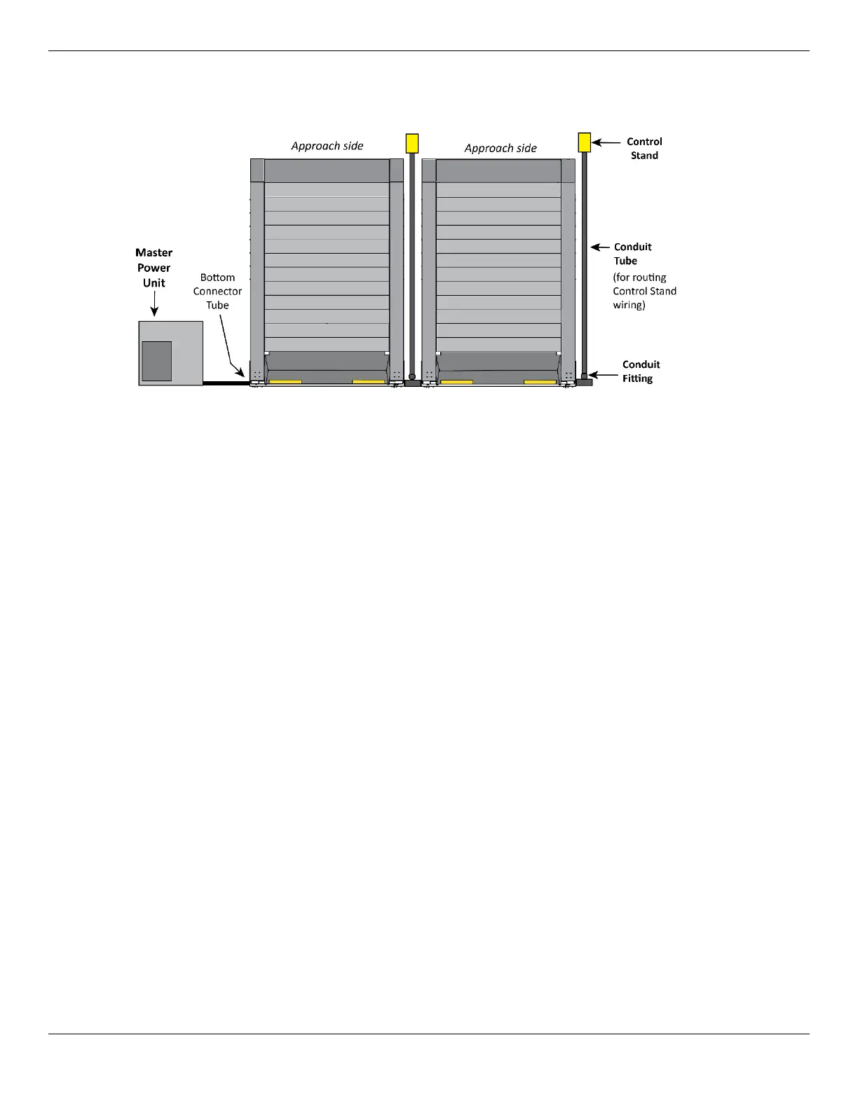
The following drawing shows the Control Stands at the
Rear
of the Lift.
Use the Cable routing diagram on Page 56 for a more detailed routing illustration.
Top view.
Not drawn to
scale. Not all
components
are shown.
To install the Control Stand at the
Rear
of the Lift:
1. Find the 14-6 Cable and route it through the Bottom Connector Tube to the Conduit Fitting.
2. Use the 16-2 Cable to connect the Solenoids near the bottom of each Cylinder (two per Lift).
3. Route the 14-8 and 16-2 Cables all the way through the Conduit Tube, then attach the Cables to
the 14-6 wiring (coming out of the Bottom Connector Tube).
4. Remove the Cover of the Control Box to have access to the wiring inside.
5. Find the Control Stand, then route the other end of the 14-8 and 16-2 (that was routed through the
Conduit Tube) through the opening in the Control Stand.
6. Connect the wires to the Controls inside the Control Box.
7. Once the wiring is routed through the Conduit Tube and connected to the Control Box, connect
the Conduit Tube to the Control Stand.
8. Attach the Control Box to the Control Stand, as described in the previous procedure.
9. When you are ready to anchor the Control Stand, use the two holes on the Control Stand Base to
mark the locations on the ground.
10. Move the Control Stand out of the way, then drill two holes 3/8" diameter by 4" (102 mm) deep in
the concrete floor at the locations you marked.
Go in straight; do not let the drill wobble. Use a carbide bit (conforming to the current
ANSI B212.15).
11. Remove all dust from the holes.
12. Use a wire brush, vacuum, hand pump, or compressed air. Do
not
ream the hole. Do
not
make
the hole any wider than the drill made it.
13. Move the Control Stand in place over the two holes, then insert an Anchor Bolt with a Washer into
each hole, tapping it down into the hole.
14. Wrench the Anchor Bolt clockwise to the recommended installation torque, 25-30 pound feet,
using a Torque Wrench.