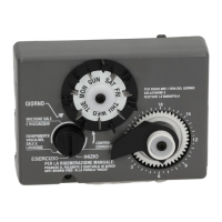
14
control. There is a locating rib on the camshaft.
Position the rib on the top of the shaft and slide the
camshaft into the control. Push up on the end of
the camshaft, furthest from the timer, snapping it
into place.
Figure 17
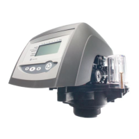
Preventive Maintenance
Figure 18
Water Meter Maintenance
Note: A water meter is used only with the 960F control.
If you are using the 440i or 940F control, this section
does not pertain to your conditioner.
The metering device used with the 960 demand
controls may require simple maintenance. In rare
instances, the turbine wheel of the water meter can
collect small particles of oxidized iron, eventually
preventing the wheel from turning.
1. Shut off the water supply or put the bypass valve(s)
into the bypass position.
2. Relieve pressure by opening the Backwash Drain
Valve (the seventh back from the control) with a
screwdriver (Figure 14).
3. Loosen and remove the pipe/tube adapters or
1265 bypass from the inlet and outlet of the valve
body.
4. Using a needle-nose pliers, remove the turbine
from the outlet housing. Grasp one of the four
vanes of the outer gland and pull straight out to
remove turbine assembly from the outlet of the
valve (Figure 18).
5. Carefully remove the turbine wheel from the
housing. Use a toothbrush to lightly scrub the iron
off the magnet. Iron buildup on the surfaces can be
removed by soaking the wheel in a mild sodium
hydrosulfite (such as RoVer*) solution for a few
minutes. Flush thoroughly with water.
6. Carefully reinstall the turbine wheel into the turbine
cage housing. Make sure that the shaft of the wheel
seats into the bearing of the cage. Reassemble the
turbine cage and check that the wheel rotates
freely.
7. Reinstall the turbine cage into the outlet of the
valve.
8. Reinstall the pipe/tube adapters or 1265 bypass to
the inlet and outlet of the valve.
9. Turn on the water supply or put the bypass valve(s)
into the service position and purge the air out of the
system.
To check for proper meter operation, open a
downstream faucet and observe the water flow
indication on the control display.
Injector
Injector Screen
Cap
Turbine
 Loading...