4
7-inch (18-cm) loop at the far end of the line so that
the bottom of the loop is level with the drain line
connection. This will provide an adequate siphon
trap.
5. Where the drain empties into an overhead sewer
line, a sink-type trap must be used.
IMPORTANT: Never insert drain line into a drain, sewer
line or trap. Always allow an air gap between the drain
line and the wastewater to prevent the possibility of
sewage being back-siphoned into the conditioner.
Figure 3
Note: Standard commercial practices have been
expressed here. Local codes may require changes to
these suggestions.
Placing Conditioner into Operation
After all previous steps have been completed the unit is
ready to be placed into operation. Follow these steps
carefully.
1. Remove control valve cover.
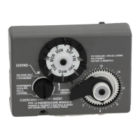
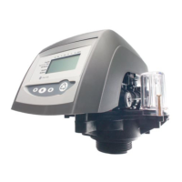
Note: The following steps will require turning the
indicator knob (Figure 4 and Figure 5) or the cycle
indicator (Figure 7) to various positions. Manually
rotate the camshaft COUNTERCLOCKWISE only
until indicator knob and cycle indicator points to
desired position. (See manual regeneration
sections for each control’s manual operation.)
2. Rotate indicator knob or cycle indicator
COUNTERCLOCKWISE until it points directly to
the word BACKWASH.
3. Fill media tank with water.
a. With water supply off, place the bypass valve(s)
into the “service” position.
b. Open water supply valve very slowly to
approximately the 1/4 open position.
IMPORTANT: If opened too rapidly or too far, media
may be lost. In the 1/4 open position, you should hear
air escaping slowly from the drain line.
c. When all of the air has been purged from the
tank (water begins to flow steadily from the
drain), open the main supply valve all the way.
d. Allow water to run to drain until clear.
e. Turn off water supply and let the unit stand for
about five minutes. This will allow all trapped air
to escape from the tank.
4. Place the conditioner into operation.
a. Advance the indicator knob or cycle indicator
COUNTERCLOCKWISE to the SERVICE
position and run water from a nearby faucet
until the water is clear.
Electrical Connection
100 VAC, 115 VAC, and 230 VAC units: Remove twist
tie from the power cord and extend cord to its full
length. Make sure the power source matches the rating
printed on the control. Be certain a wall switch does not
control the outlet.
12 VAC: Connect the plug of the transformer (supplied)
secondary cable to the mating socket at the rear or
bottom of the timer housing. Be certain the transformer
is secure and is plugged into a power source of correct
voltage that is not controlled by a wall switch.
Right Way