AUX DC Inverter Free Match 50HZ R32
77
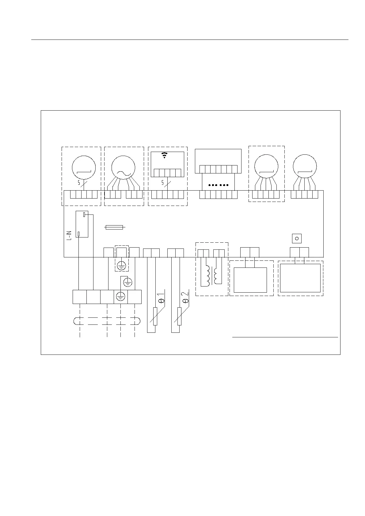
Part6 Electrical Principle Diagram
1. Wall Mounted
1.1 L Type (07K, 09K, 12K, 18K)
NO TE: "Lo" on the term inal block does not need to be connected.
Dotted line part in the fram e m ay not be used.
DC Fan M otor
AC Fan M otor
W IF I M o d u le
Display receive panel
Step M otor
Step M otor
FU SE
3.15A 250V
PC B
Forced Sw itch
T ra n sfo rm e r
A nion
H ig h V o lt a g e
G enerator
E le c tro sta tic
D u ste r
Tem perature Sensor
To O utdoor Unit
B ro w
L
N
PE
C
Red
B lu e
Y /G
B la c k
L
L
0
S
N
Som e m odels have no content inside dashed fram e
16437010000237
Indoor Unit Electric C hart
M 1 M 2
M 4 M 3
 Loading...