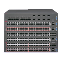
The switch has four bays and you can choose any one of them to install a module. The switch
detects where the modules are installed so the order is not important.
You can also install a new module or hot swap an existing module while the switch is operational.
Note:
When looking at the front of the switch, slot numbering begins at the top row and increases from
left to right. Slot 1 is the top-left slot; slot 2 is the top-right slot. Slot 3 is the bottom-left slot; slot
4 is the bottom-right slot.
Before you begin
To prevent damage, handle the ESMs carefully by using the following guidelines:
• To prevent damage from electrostatic discharge, always wear an antistatic wrist strap
connected to an ESD jack.
• Always place the modules on appropriate antistatic material.
• Support the module from underneath with two hands. Do not touch components or connector
pins with your hand, or damage can result.
• Visually inspect the connectors for damage before you insert the module. If you insert a module
with damaged connectors you will damage the switch.
• Do not stack modules one on top of the other when you move them.
• Do not leave bays open. Fill all bays with modules or module bay covers to maintain safety
compliance, proper cooling, and EMI containment.
• Do not over tighten screws. Tighten until snug. Do not use a power tool to tighten screws.
Procedure
1. Remove the two screws that secure the module bay cover to the chassis. (Save the module
bay cover for possible future use.)
Ethernet Switch Module
November 2016 Installing the Avaya VSP 8000 Series 27
Comments on this document? infodev@avaya.com

 Loading...