Installation fundamentals
VSP 8200
The VSP 8200 consists of:
• eighty 10GBASE-SFP/SFP+ ports
• four 40GBASE-QSFP+ ports
• one 10/100/1000BASE-T Out-Of-Band Management Port
• one RJ-45 Console Port
• one USB 2.0 port
• Base Software License
• one field-replaceable 800 watt power supply (either AC or DC)
• four field-replaceable 12 volt fan modules
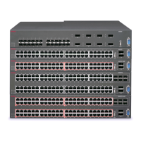
Figure 1: VSP 8284XSQ — Front view
1. SFP+ port LEDs are in between the ports on each slot. The up arrows refer to the port above and the
down arrows refer to the port below. For a description of what the LEDs mean, see SFP, SFP+, and QSFP+
port LED state indicators on page 84.
2. Eighty SFP+ ports that support Avaya’s 1G SFPs and 10G SFP+s.
•
40 ports in Slot 1 on top
• 40 ports in Slot 2 on the bottom
3. QSFP+ port LEDs are in between the ports on each slot. The up arrows refer to the port above and the
down arrows refer to the port below. For a description of what the LEDs mean, see
SFP, SFP+, and QSFP+
port LED state indicators on page 84.
4. Four QSFP+ ports: two in Slot 1 and two in Slot 2.
5. USB port
6. Console port
Table continues…
Installation fundamentals
November 2016 Installing the Avaya VSP 8000 Series 21
Comments on this document? infodev@avaya.com

 Loading...