7. Management port — The LEDs are on the bottom of the port. For more information, see Management port
LEDs on page
83.
8. LEDs for system power (PWR), switch status (Status), redundant power supply (RPS), and fan modules
(Fan). For more information, see Switch LEDs on page 82
.
The following figure shows the rear of the chassis with four fan modules and one power supply
installed. The fan modules are numbered 1–4 from left to right, and the power supplies are
numbered PSU 1 on top and PSU 2 on the bottom.
Figure 2: VSP 8284XSQ — Rear view
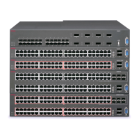
VSP 8400
The VSP 8400 consists of:
•
four slots to install ESMs. For more information, see
Ethernet Switch Module (ESM). on
page
24
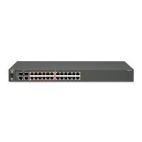
• one 10/100/1000BASE-T Out-of-Band Management port
• one RJ45 console port
• one USB 2.0 port
• one field replaceable 800 watt power supply (AC or DC)
• four field replaceable 12 volt fan modules
• Base Software License
The following figure shows the front view of the VSP 8404.
Installing the Avaya Virtual Services Platform 8000 Series
November 2016 Installing the Avaya VSP 8000 Series 22
Comments on this document? infodev@avaya.com

 Loading...