Note:
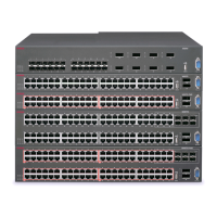
When looking at the front of the switch, slot numbering begins at the top row and increases from
left to right. Slot 1 is the top-left slot; slot 2 is the top-right slot. Slot 3 is the bottom-left slot; slot
4 is the bottom-right slot.
Figure 3: VSP 8404 Front view
1.
Displays the four slots to install ESMs. For more information on ESMs supported in this
current release, see
Ethernet Switch Module (ESM) on page
24. The table below shows
the part numbers for the ESMs:
ESM Part number
1/10GBASE-SFP+ 8424XS - EC8404001-E6
8424XS (GSA version)- EC8404001-E6GS
100M/1G/10GBASE-RJ45 8424XT - EC8404002-E6
8424XT (GSA Version) - EC8404002-E6GS
40GBASE-QSFP+ 8408QQ - EC8404003-E6
8408QQ (GSA Version) - EC8404003-E6GS
1/10GBASE-SFP+ and 40GBASE-QSFP+
combination
8418XSQ - EC8404005-E6
8418XSQ (GSA Version) - EC8404005-E6GS
1/10GBASE-T and 40GBASE-QSFP+
combination
8418XTQ - EC8404006-E6
8418XTQ (GSA Version) - EC8404006-E6 GS
100/1000M-SFP 8424GS - EC8404007-E6
8424GS (GSA Version) - EC8404007-E6GS
10/100/1000M-RJ45 8424GT - EC8404008-E6
8424GT (GSA Version) - EC8404008-E6GS
2. LEDs for system power (PWR), switch status (Status), redundant power supply (RPS), and
fan modules (Fan).
3.
USB port
4. Console port
Installation fundamentals
November 2016 Installing the Avaya VSP 8000 Series 23
Comments on this document? infodev@avaya.com

 Loading...