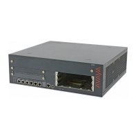
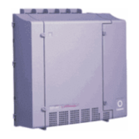
Removing the G430 cover
About this task
Voltage:
Disconnect the G430 from the external power source before proceeding.
Electrostatic alert:
Do not touch any components on the printed circuit board.
Procedure
1. Disconnect the G430 power cable from the mains power supply.
2. Note to which connector each cable is connected, so that you can reconnect them
correctly.
3. Disconnect all cables (data and power) connected to the G430 and the media
modules, both front and rear.
4. Remove the G430 from the rack or wall, if it is wall or rack mounted.
5. If mounting brackets are attached to the G430, remove them.
6. Unscrew the 8 cover screws, indicated by small arrows etched into the cover:
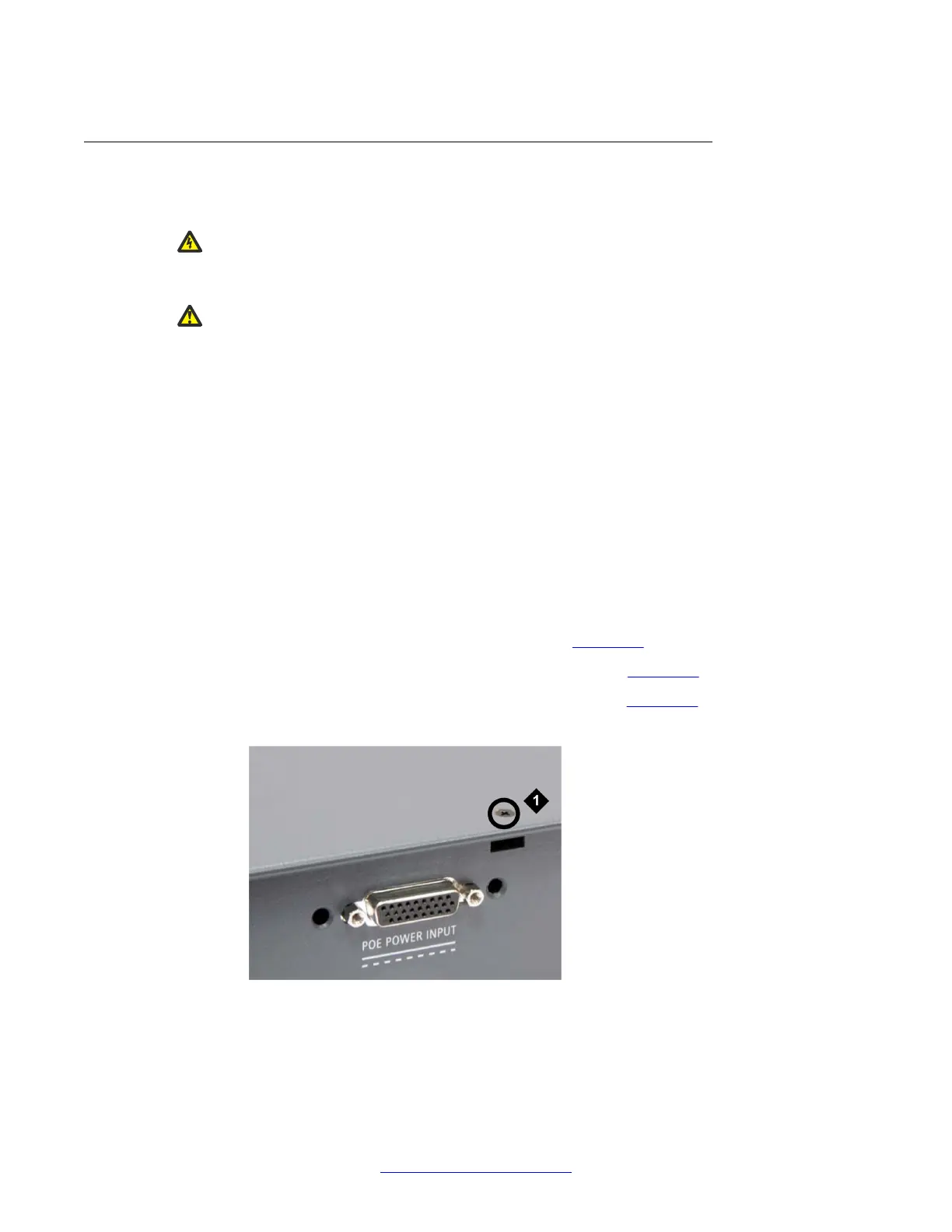
• Remove one screw from the top (see the figure on page 22).
• Remove four screws from the right side (see the figure on page 23).
• Remove three screws from the left side (see
the figure on page 23).
7. Lift the cover off the G430.
Figure 5: Removing the G430 cover screw from the top of the device
Installing the MP120 VOIP module
22 Configuring V.150.1 on Avaya G450 and G430 Branch Gateway May 2014
Comments? infodev@avaya.com


 To Next Page