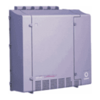
• Three screws on the left side (see the figure on page 22).
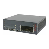
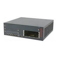
3. Attach the mounting brackets to the G430, if applicable.
4. Replace the G430 in the rack or mount on the wall, if applicable.
5. Re-connect all cables (data and power) that you disconnected from the G430 and
its media modules, both front and rear.
6. Connect the G430 power cable into a mains socket.
7. Use the show platform mainboard CLI command to make sure the G430 is
working properly.
For example, when the G430 is working properly, output includes:
MAINBOARD BOARD
---------------
Type : G430
Description : Avaya Inc., G430 Media Gateway
Serial Number : 08IS26191007
HW Vintage : 4
HW Suffix : F
FW Version : 29.18.0
No Fault Messages : No Fault Messages
When a VoIP module is successfully installed in the optional VoIP module slot,
output for the slot includes:
MEDIA SOCKET #2
------------------
Type : MP80 VoIP DSP Module
Description : VoIP DSP resource with 80 channels
Serial Number : 07IS15812717
HW Vintage : 0
HW Suffix : B
Faults : No Fault Messages
When no VoIP module is installed in the optional VoIP module slot, the output for
the slot includes:
MEDIA SOCKET #2
------------------
Type : UNKNOWN
Description : UNKNOWN
Serial Number : UNKNOWN
HW Vintage : UNKNOWN
HW Suffix : UNKNOWN
Faults : NOT PRESENT
Adding and removing the MP120 VOIP module
Configuring V.150.1 on Avaya G450 and G430 Branch Gateway May 2014 27


 To Next Page