15
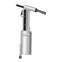
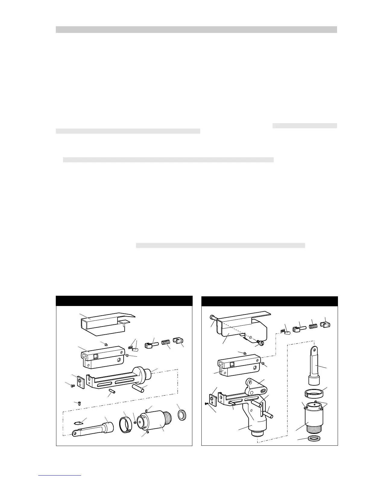
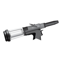
STRAIGHT SWIVEL NOSE ASSEMBLY
RIGHT-ANGLE SWIVEL NOSE ASSEMBLY
2
1
15
9
8
8
10
7
11
17
18
19
20
3
16
16
4
12
14
13
6
6
5
16
1
3
12
14
13
16
6
5
21
22
11
7
9
8
8
8
10
17
18
19
20
■
■
■
■
■
■
■
■
■
■
■
■
■
■
■
0 7 3 4 5 & 0 7 3 4 6 M O D E L S
As described on pages 6 and 7 the fitting of a straight swivel nose assembly to a 07340-00200 base tool will create a 07345 tool model
and the fitting of a right-angle swivel nose assembly to the same base tool will create a 07346 tool model. Because there are few
differences between the two nose assemblies, the fitting and servicing procedures are almost identical.
FITTING INSTRUCTIONS
The following procedure will allow you to fit either of the swivel nose assemblies (
as illustrated below
) to the tool. If you order a complete
nose assembly rather than individual components, you will only need to start at stage ■.
All moving parts should be lubricated. Unless stated otherwise use Moly lithium grease (
details page 17
). When on grey tint, instructions
refer only to the right-angle nose assembly fitted to 07346 models.
Fit locking ring 10, detailed below, over jaw spreader housing of tool (item 47 page 22).
Coat screw 13 with thread locking adhesive and use to secure nose tip 14 onto body 5.
Lightly lubricate items 17,18,19,20 and insert into jaw carrier 3 as shown. Secure with screws 16.
Position lever 4 into body 5 and hold in place with pin 15 through the hole of body 5 (not a slot).
Lubricate the sides of the jaw carrier assembly and insert into body 5.
Lubricate rollers 8 and ENSURE that they will freely rotate in the holes of adaptor 9. If necessary ream the holes.
Position spring clip 7 over adaptor 9 past the holes for the rollers and rotate until the locating peg is aligned with the corresponding
hole in adaptor 9 (smallest hole).
Fit adaptor 9 over the end of body 5 and drop rollers 8 into place. Push spring clip 7 over rollers 8.
Insert spindle 11 through adaptor 9 into jaw carrier 3 until the hole lines up with slot in body 5. Temporarily hold in place with pin 6.
Insert pin 12 through the front slot of body 5 into jaw carrier 3.
Hold the assembly vertical to prevent all pins dropping and slide the jaw carrier assembly back and forth a few times to ensure
free movement.
Push pin(s) 6 out and let spindle 11 drop out. Screw spindle 11 onto the jaw spreader housing of the tool, leaving the small screw
fixing hole uppermost for straight swivel nose assemblies. Tighten gently with a tommy bar.
Screw the assembly over spindle 11 onto the tool handle. Replace pin(s) 6.
On straight swivel nose assemblies attach platform 22 onto the top of the spindle with screw 21. Deburr the back end of platform
22 so that it cannot catch on guard 1.
Snap guard 1 over the assembly, carefully sliding cut-out around the head of screw 15 and secure with screw 2.