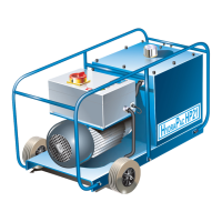
9
Mechanical Maintenance
Assembly (continued)
Final Assembly
• Connect the steel pipe to the pump and valve set and tighten using a 20 mm spanner.
• Connect the solenoid wire to its terminal block using a 3 mm flat screwdriver. Place the block in position on the solenoid and
secure with the screws provided.
• Ensure that the oil drain plug has been replaced and tightened using a 13 mm spanner.
• Fill to the maximum level indicated on the Oil Level Indicator 5 with the grade of hydraulic fluid stipulated in the Technical
Specifications on page 5.
Pressure Setting
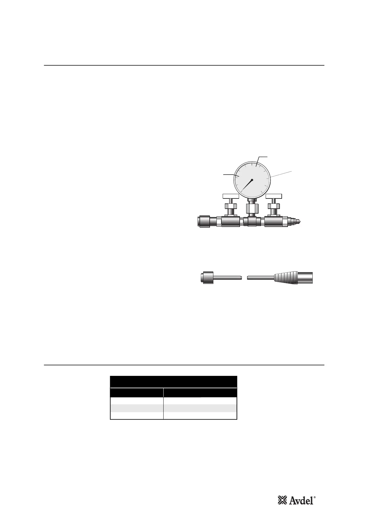
• Connect the Pressure Setting Gauge Set and Hoses (73010-00003)
to the HydraPac.
• Plug in the Setting Trigger 73010-00004 (see illustration below).
• Place the Tank Cover Assembly 35* loosely in position. This is to
prevent excessive oil splash during setting.
• Connect to the HydraPac power supply and switch on.
• Turn the Isolator 12 on the Enclosure Assembly 32 to 'On'.
• Ensure that both needle valves on the Pressure Setting Gauge Set
are fully open.
• Depress and release the trigger a few times allowing the oil to
circulate freely. This will remove all the air from the hydraulic
system and also indicate if the directional valve is functioning.
• Keeping the Trigger Switch depressed, slowly close the Needle
Valve 'A' reading the pressure on the gauge take note of the
pressure when the release valve opens. Adjust the screw on the left
hand side Spring Dome, (the lower of the two domes) to obtain the
setting given on the Gauge Set illustration. Once the correct
pressure setting has been achieved, lock the adjusting screw in
place with the nut provided using a 10 mm spanner.
• To set the Return Pressure repeat as in previous step but with the
Trigger Switch released. Needle Valve 'A' must be fully open and
Needle Valve 'B' utilised to obtain the setting. Adjustments for the pressure are to be made on the second Spring Dome.
• On completion of the pressure settings, replace and secure the Tank Cover Assembly 35* with the 10 mm socket head cap
screw using a 5 mm allen Key and reset the timer if need be.
Note: It may be necessary during Pressure Setting to temporarily increase the delay time on the "Sleep Mode" Timer.
Item numbers in bold refer to the General Assembly and Valve Set drawings and Parts Lists on pages 10 - 16.