- 21 -
been replaced. The system cannot be connected.
• In connected mode: a last and definitive alarm cycle, without the activation of the buzzer output. The
control panel functions are fully reset as soon as the battery conditions return to be normal. The low
battery alarm and/or fuse triggering are stored like any other alarm; it makes the activation point red
LED flash immediately and makes all the zone and tamper LEDs flash on the control panel as soon as
the system is disconnected. At this point, to reset the memory it is necessary to enable the system as
for any other alarm.
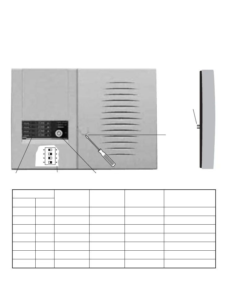
DESCRIPTION OF THE FRONT PANEL AND INDICATIONS
(Fig. 1)
The table shows the meaning of the visual indications seated on the control panel.
Note: The alarm indication LEDs are always OFF when the control panel is ON. The fast flashing indica-
Mechanical key
closing screw
(under the plastic
plug)
Anti-removal
tamper
pushbutton
Timer microswitches
Zone exclusion zones
LED
ON OFF
FLASHING FLASHING
Function Colour fast slow
Power Green Mains present Mains absent
On Green Control panel ON Control panel OFF
Tamper Red Tamper open Tamper closed Alarm stored
Zone A1 Red Zone A1 open Zone A1 closed Zone A1 excluded Zone A1 alarm stored
Zone A2 Red Zone A2 open Zone A2 closed Zone A2 excluded Zone A2 alarm stored
Zone B Red Zone B open Zone B closed Zone B excluded Zone B alarm stored
Zone C Red Zone C open Zone C closed Zone C excluded Zone C alarm stored
front view
side view