- 21 -
OPERATING DESCRIPTION
Mechanical key and exclusion zone pushbuttons
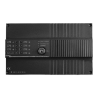
As shown in Fig. 1, the control panel is equipped with a mechanical key with 10,000 combinations /2
positions:
• ON for the control panel in service
• OFF for the control panel at rest
The key can be taken out in both positions. The control panel can be connected with all the zones acti-
ve or in a zoned mode by excluding some of them. When the key is in the OFF position, zones can be
selectively excluded using the exclusion pushbutton P1.
Pressing P1 for 2 seconds the zone LEDs switch on in sequence and remain on for 2 seconds, starting
from A1 up to C2. During the LED switching on, the related zone can be excluded by pressing P1 short-
ly again. As shown in table on page 23, when a zone is excluded the related LED flashes quickly, whe-
reas when a zone is enabled its LED is OFF and remains in this status up to the next programming. If,
after pressing the pushbutton for the first time and for 2 seconds, P1 is not pressed again any more, all
zones remain automatically enabled and their LEDs are OFF. After carrying out this operation, the
system is connected by turning the key to the ON position. During the exit time, the LEDs of the con-
nected zones remain ON, whereas the LEDs of the excluded zones are OFF
Timers
Three timers are provided for and can be adjusted by their microswitches positioned on the board, as
shown in figure 1.
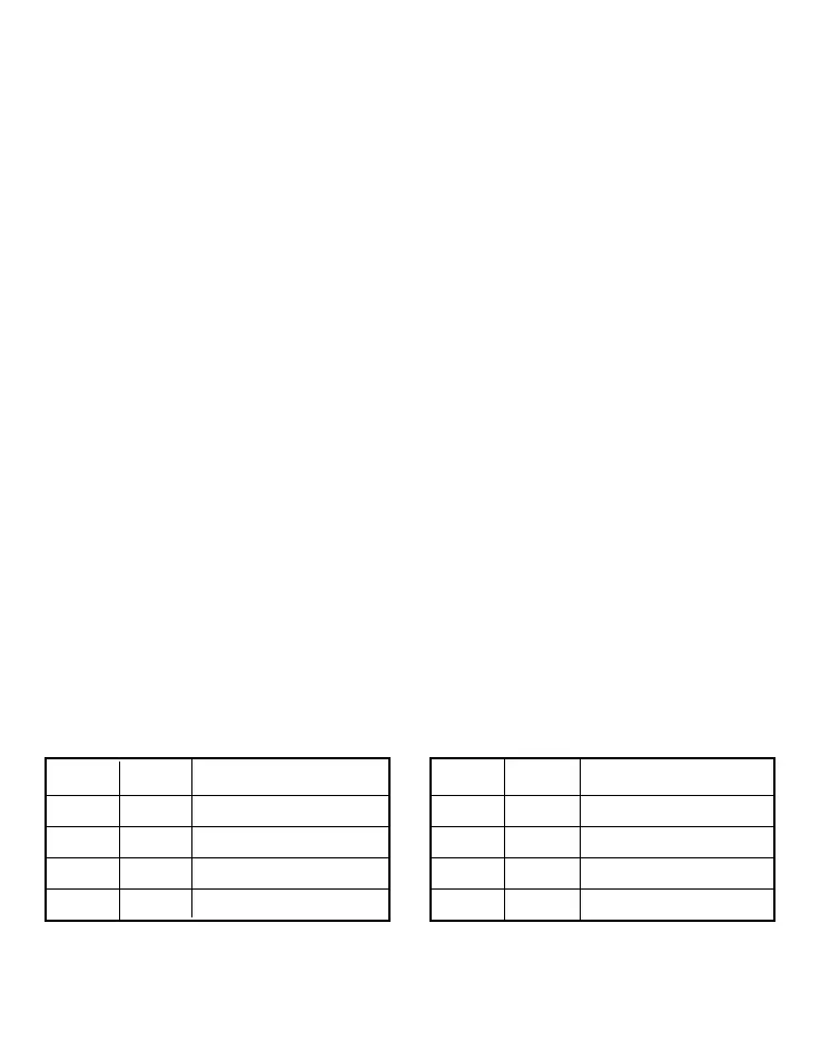
1) Entrance time: 1. this is the interval from the opening of delayed zone A1 until the control panel
activates the sirens. Using SW1 and SW2 microswitches, it can be set to one of the following values:
2-20-40-60 s. (as shown in table 1)
2) Alarm time: Alarm time: this is the siren sounding time. Using SW3 and SW4, it can be set to one
of the following values: 1-60-120-240 s. (as shown in table 2)
3) Exit time: Exit time: this is the time during which the system remains disabled upon connection. This
is fixed and is equal to 60 s; it automatically changes to 4 s. when the entrance time is set to 2s.
Note: If the delayed line A1 is placed in alarm first, the entrance delay set is extended to all the lines.
SW1 SW2 Entrance time
OFF OFF 2 s
OFF ON 20 s
ON OFF 40 s
ON ON 60 s
SW3 SW4 Alarm time
OFF OFF 1 s
OFF ON 60 s
ON OFF 120 s
ON ON 240 s
Table 1 Table 2