- 31 -
REMOTE ACTIVATION POINT
Refer to page 24 of the present manual for the description of the remote activation point.
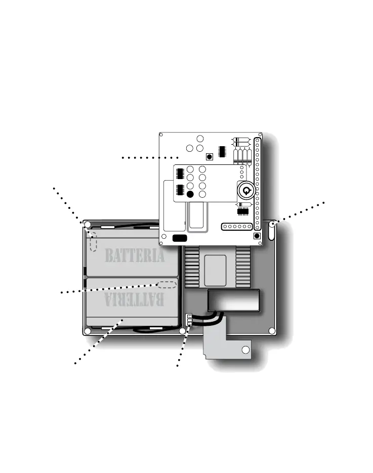
MAINS AND BATTERY CONNECTIONS
The control panel 12v/1.2Ah internal battery is composed of two 6v/1,2 Ah (cod. AF910) batteries con-
nected in series in order to obtain one battery.
Connect the positive pole (red) of one battery to the negative pole (black) of the other one using the
connection cable supplied with the control panel.
Then, insert the batteries in their position as shown in fig. 2. Finally, connect the mains (230Vac) to
the two terminals seated on the power supply board, as shown in fig. 2.
CONNECTION TERMINAL BLOCK (page 32) AND APPLICATION DIAGRAM (page 1B)
The terminal block is composed of No. 26 screw terminals with bracket tightening (rating 2.5 mm2) of
the conductor.
Note: if one of the 7 zones is not used, close the zone by connecting a jumper to the terminal board
between the input of the zone and the GND.
Wall fixing hole
Main board
Wall
fixing
hole
Wall fixing hole
Battery seat
230Vac connection terminal block
FIG. 2