37
3INSTALLATION AND DEINSTALLATION
2.2 CONNECTING THE SENSORS
ALS
20X
256
Enabling
Set MACHINE SETUP > OD sensor warn. to „Warning“.
Set MACHINE SETUP > OD Sens.polarity to „Level low ac-
tive“.
If the optional applicator interface board is installed, but
the standard signal interface is supposed to be used:
Set SIGNAL INTERFACE >ACTIVE INPUTS > OD sensor sig-
nal to „Default input“.
Setting the roll diameter
Prerequisite:
– OD sensor is installed an activated.
– Label material roll with the required remaining dia-
meter is prepared.
Measure the diameter of the prepared roll.
Loosen the thumb screws [56A] at the reflector
[56B].
Shift the reflector to the upper [55B] or lower [55A]
position (long holes) according to the measured roll
diameter (--> tab.). Retighten the thumb screws.
Insert the prepared label roll.
Loosen the thumb screws at the sensor [56C].
Rotate the sensor to the top, until the light beam
does not meet the reflector any more.
– The LED at the sensor is off.
Slowly rotate the sensor down, until the light beam
meets the reflector.
– The LED at the sensor lights up.
Rotate the sensor further down, until the light beam
is covered by the label roll.
– The LED at the sensor goes out.
Tighten the thumb screws.
Roll Ø
in mm
Roll Ø
in Inch
Reflector
position
38-122 1,5-4,8 Up
51-135 2,0-5,3 Down
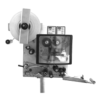
[55] Setting the OD sensor
A Lower reflector position
B Upper reflector position
C Rotating range of the sensor
[56] Thumb screws (A, C) which have to be loosened to set the
sensor.
 Loading...