XR Series Installation Instructions 13
3.1 Installing the XR 4500, XR 4500TL or XR 6500
5. Run power and communication cables into the enclosure via strain reliefs (as
required).
Wall Mounting
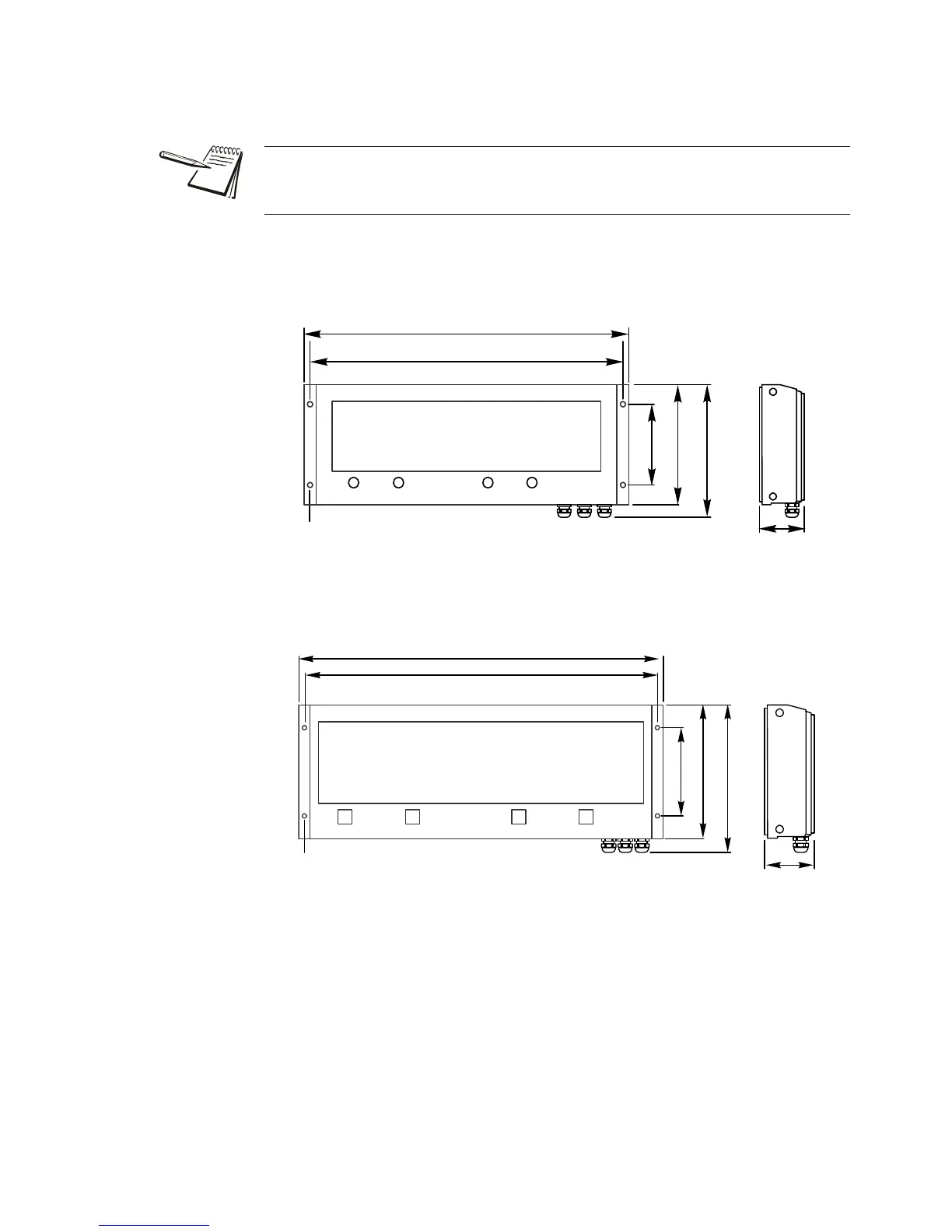
Hole patterns for the XR series are given in Figure 3.4 and Figure 3.5.
Figure 3.4 XR 4500 Outline dimensions and hole pattern
Figure 3.5 XR 4500TL and XR 6500 Outline dimensions and hole pattern
Pole Mounting Bracket
1. Select appropriate height and fasten the small “C” bracket to the pole using the
mounting clamps provided.
2. Fasten the larger “C” bracket to the small “C” bracket using the hardware
provided.
The electronics carriage may be removed to reduce weight when installing.
Mounting hole size in the case is 3/8”.
Dia: .375in.[9.5mm]
24.00in.[609.6mm]
23.00in.[584.2mm]
10.125in.[257.2mm]
8.88in.[225.6mm]
6.00in.[152.4mm]
Dia: .375in.[9.5mm]
32.00in.[812.8mm]
31.00in.[787.4mm]
13in.[330.2mm]
11.75in.[298.4mm]
7.75in.[196.9mm]
 Loading...