S6L Control Surface RAM Expansion 16
Complete the Installation
Re-install the back cover to complete the installation. For details and illustrations, refer to the earlier instructions for disassembly.
To re-assemble the S6L-24C and 16C:
1 Reconnect the light cables (refer to Disconnect Light Cables).
2 Reinstall the top panel and secure it with the 4 fasteners you removed earlier.
3 Reinstall the back cover and secure it with the fasteners you removed earlier.
4 If you loosened or removed one or both End Caps, re-install them and tighten their fasteners. If you removed either or both End
Caps, be sure to re-connect the LED cable(s).
5 Proceed to Confirm the Installation.
To reassemble the S6L-24D, 32D, or 48D control surface:
1 Making sure to orient the back cover correctly, slide the cover back into position on the control surface.
2 Reinstall the fasteners to secure the back cover to the S6L chassis.
3 If you loosened or removed a retaining bracket and/or one or both End Caps, re-install them and tighten their fasteners (be sure
to re-connect the End Cap LED cables).
4 Proceed to Confirm the Installation.
Confirm the Installation
After re-assembling the control surface, reconnect your system (connect the control surface to the E6L engine, and connect all
Stage I/O units), then power the system on and verify that the system date and time are set correctly.
Power up the system in the following sequence:
1 Power on the control surface video monitor (referred to in this and other S6L guides as the external screen).
2 Power on the E6L engine by pressing the power switch on the back to the on (1) position. On the front panel of the E6L engine,
the LEDs light as follows:
• Status LED lights green.
• The System LED begins to flash amber while the E6L is waiting to connect to the S6L control surface.
3 Power on the S6L control surface by pressing the power switch on the back panel to the on (1) position.
4 When the system has connected, go to Options > System and click on the displayed VENUE software version. Confirm that the
newly installed RAM is listed in the banner area at the lower left-hand corner of the external screen.
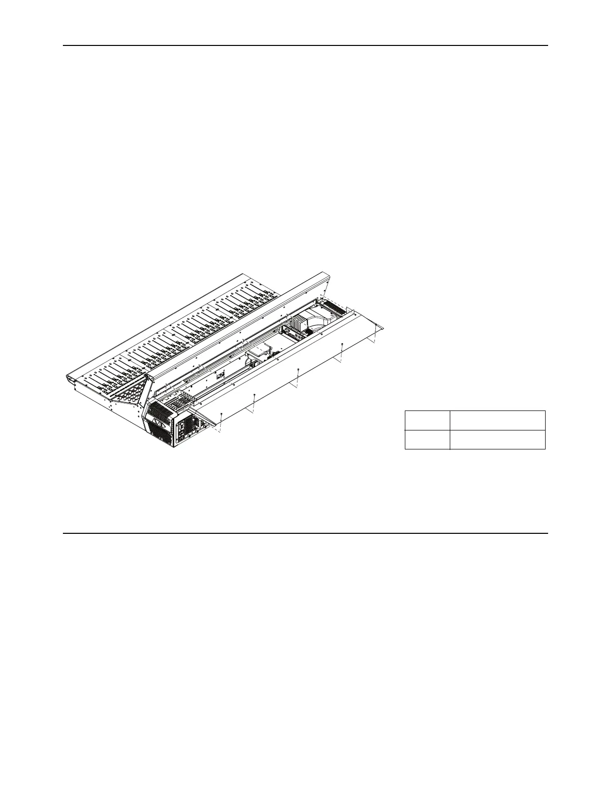
Figure 33. Replacing the S6L back cover (S6L-32D shown)
Fasteners:
Tool:
M4x8mm BHCS
2.5mm Hex driver

 Loading...